Eureka AIR delivers breakthrough ideas for toughest innovation challenges, trusted by R&D personnel around the world.

An underwater imaging device and method using laser spot scanning

An imaging device, laser point technology, applied in optics, image communication, optical components, etc., can solve the problems of complex linear or strip light source structure, difficult to realize underwater robot, difficult to improve scanning accuracy, etc. Scattering elimination effect, low power consumption, effect of reducing backscattering

Active Publication Date: 2021-01-15
DALIAN MARITIME UNIVERSITY
View PDF14 Cites 0 Cited by
  • Summary
  • Abstract
  • Description
  • Claims
  • Application Information

AI Technical Summary

Problems solved by technology

However, this invention requires that the distance between the imaging unit and the light source be greater than 1 / 2 of the farthest imaging distance, which is difficult to achieve on most underwater robots, and once the installation position is determined, it can only image objects within a fixed distance range
In addition, compared with the laser point light source, the structure of the linear or strip light source used in this invention is more complicated, which is not conducive to practical application
Third, the scanning method using the light source array in turn in this invention has the problems of complex structure and large volume, and it is difficult to improve the scanning accuracy

Method used

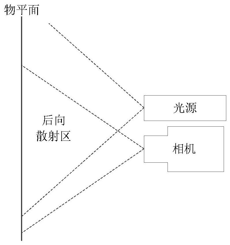
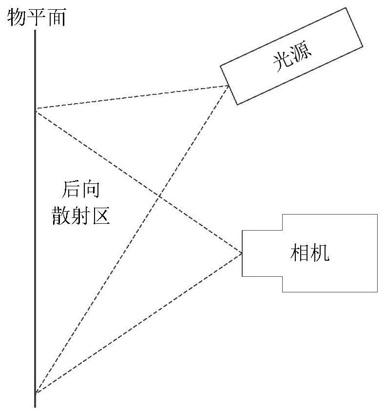
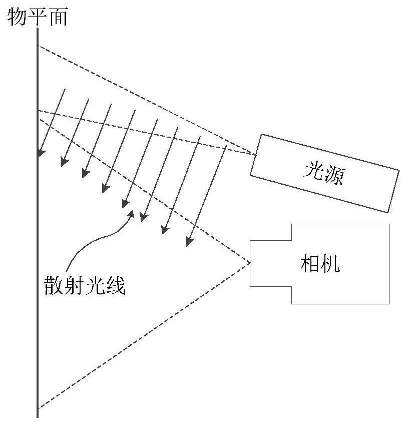

Image

  • An underwater imaging device and method using laser spot scanning
  • An underwater imaging device and method using laser spot scanning
  • An underwater imaging device and method using laser spot scanning

Examples


Embodiment Construction

[0032] The present invention will be further described below in conjunction with the accompanying drawings.

[0033] Such as Figure 4As shown, the imaging device of the present invention includes an imaging unit 1 using a rolling shutter exposure method and a laser point scanning light source. The imaging unit 1 and the laser point scanning light source are connected through a synchronization cable 3 and a synchronization circuit 4 . The light source 2 is placed directly above the imaging unit 1, but this is not the only way of placement. The laser point scanning light source includes a semiconductor laser module 5, which can generate a laser beam 7, and the laser beam 7 can contain one wavelength or multiple wavelengths. The laser point scanning light source also includes a two-dimensional micro vibrating mirror 6 . The laser light 7 emitted by the semiconductor laser module 5 is reflected by the micro-vibration mirror 6 to the plane 8 where the target is located, forming ...


PUM


Abstract

The invention discloses an underwater imaging device and method using laser point scanning. The device includes a light source, an imaging unit and a synchronous circuit; the light source is a laser point scanning light source, and the laser point scanning light source includes A semiconductor laser module; the imaging unit is a camera or video camera with a CMOS image sensor with a rolling shutter exposure function; the whole set of devices is placed on the same side of the object to be photographed. The present invention uses a laser point scanning light source, which has a simpler structure, smaller volume, and higher energy utilization rate than a linear light source or a strip light source. The present invention can use multiple semiconductor lasers to synthesize a beam of laser light, which can not only increase the power of the light source, but also make the light source contain multiple wavelengths, and achieve better backscattering elimination effect by changing the wavelength of the light source under different water qualities, or Color correction effect. The invention has higher scanning speed, lower power consumption, higher stability and smaller volume.

Description

technical field [0001] The invention relates to the technical field of imaging equipment, and in particular to an underwater imaging device and method for illuminating by point scanning of a laser light source. Background technique [0002] Due to the characteristics of water molecules and the presence of a large number of impurities in natural water bodies, the clarity of underwater images is greatly affected by scattered light. Due to the absorption of water molecules and impurities, light attenuates quickly in water. In order to obtain digital images with appropriate brightness, underwater imaging systems often include lighting sources. However, since the light source and imaging unit are usually designed on the same side of the underwater target, the observation of the target is strongly affected by the backscattering of the water body, and the obtained image will be partially overexposed and the scene underexposed, so it is difficult to Obtain clear images of underwate...

Claims


Application Information

Patent Timeline
Patent Type & Authority Patents(China)
IPC IPC(8): G03B15/02G02B26/08G02B26/10H04N5/225
CPCG02B26/0833G02B26/105G03B15/02H04N23/56
Inventor 吴厚德赵明
Owner DALIAN MARITIME UNIVERSITY
Why Eureka
Eureka Blog
Learn More