Novel structure of flood control dam on silty-fine sand stratum

A new type of structure, silty sand technology, applied in infrastructure engineering, dams, barrages, etc., can solve the problems of insignificant flood control benefits, reduce construction difficulty, solve insufficient bearing capacity, and increase stability

Pending Publication Date: 2019-04-09
新疆水利水电规划设计管理局
View PDF11 Cites 4 Cited by
  • Summary
  • Abstract
  • Description
  • Claims
  • Application Information

AI Technical Summary

Problems solved by technology

[0005] The purpose of the present invention is to provide a new structure of flood control dams in silt and fine sand strata to solve the problem in the prior art that the existing flood control dikes in the existing silt and fine sand layer riverbeds have no significant flood control benefits

Method used


Image

  • Novel structure of flood control dam on silty-fine sand stratum
  • Novel structure of flood control dam on silty-fine sand stratum
  • Novel structure of flood control dam on silty-fine sand stratum

Examples


Embodiment 1

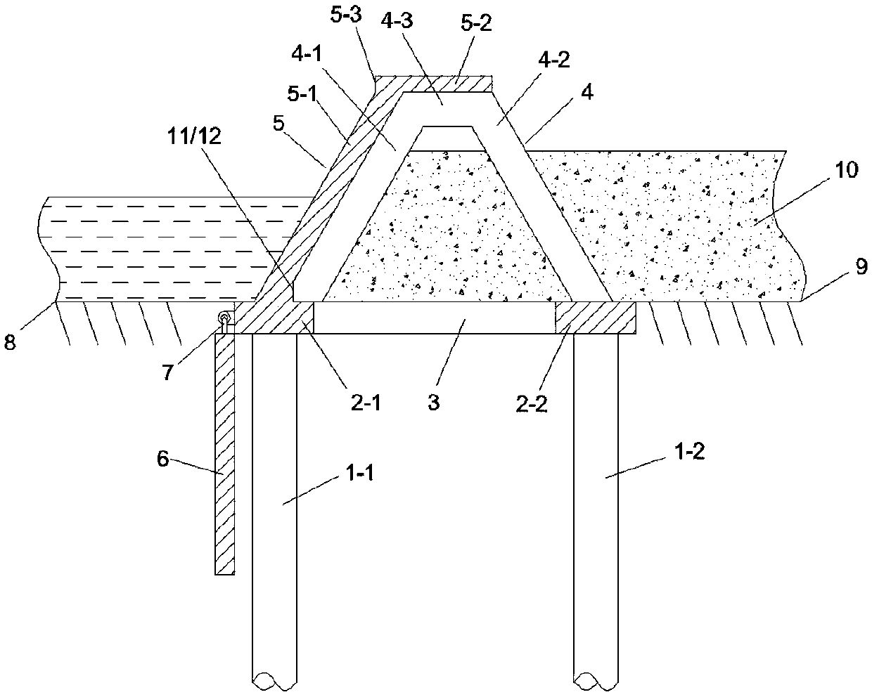
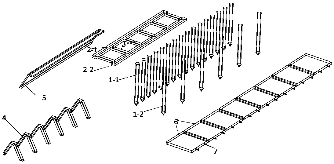
[0039] Such as figure 1 , figure 2 , image 3 and Figure 4 Shown is a specific embodiment of a novel structure of a silty sand formation flood control dam according to the present invention. In this embodiment, a straight line along the dam is adopted, the crest of the dam is allowed to overcome waves, and the angle between the dam body and the water flow is 0°. The specific structure Including: two rows of pile sinking 1-1 and 1-2 driven into the ground, the arrangement density of the inner row of pile sinking 1-1 near the river is greater than that of the outer row of pile sinking 1-2, the arrangement density of the pile sinking 1-1 , 1-2 During manufacture, use a cylindrical mold with a steel cage inside to pour concrete. During pouring, use a concrete vibrator to vibrate the concrete evenly. After demoulding, maintain it and sink the pile 1-1 , 1-2 surface anti-corrosion treatment, such as coating cold base oil. In this embodiment, pile sinking 1-1 and 1-2 adopt holl...

Embodiment 2

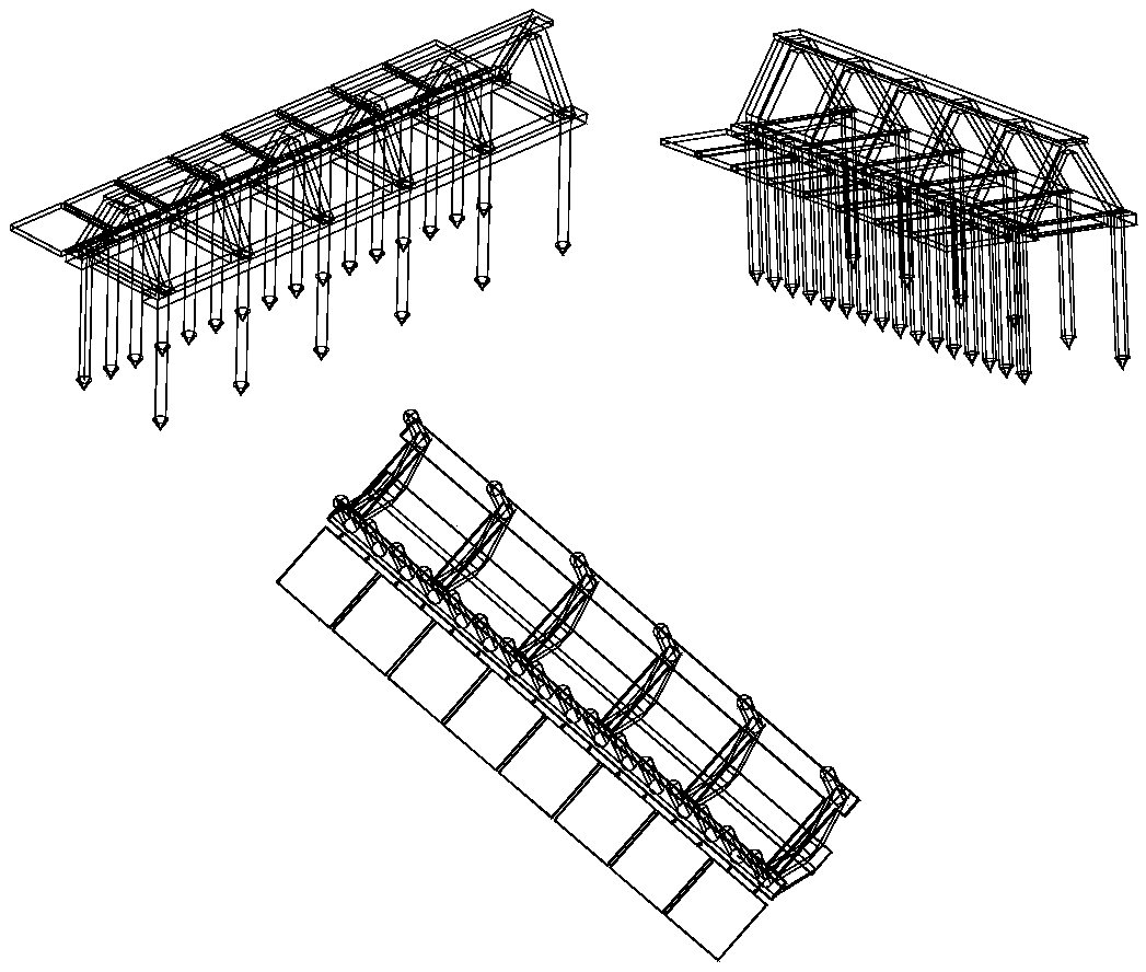
[0056] Such as Figure 5 and Figure 6 Shown is another kind of specific embodiment of the novel structure of a kind of silty sand formation flood control dam of the present invention, in the present embodiment the structure of the silt fine sand layer river section flood control dam is basically the same as the structure in embodiment 1, the same No more details here, the difference is that this embodiment also includes: arch beams 13, the arch beams 13 are prefabricated in the slope retaining wall 5-1, and are distributed continuously, the arch beams 13 are arched towards the direction of the river, Two adjacent arch beams 13 are connected by a connecting plate 14, and the position of the connecting plate 14 is set corresponding to the supporting beam 4-1. Since the slope retaining wall 5-1 has a certain height, multiple arch beams 13 can be arranged in the slope retaining wall 5-1.

[0057] This enables the slope retaining wall 5-1 between the two supporting beams 4-1 to ...


PUM


Abstract

The invention provides a novel structure of a flood control dam on the silty-fine sand stratum. The novel structure comprises an underground sunken pile structure and an overground water retaining damstructure, two rows of sunken piles are driven underground with a water jetting method, and the overground structure and the underground structure are connected through reinforcing steel bar pouringor connected by prefabricated socket nesting and addition of fasteners; #-shaped ring beams are connected with upper ends of the sunken piles and extend in the configuration direction of the sunken piles, water retaining panels are arranged on floor beams located on one side of an upstream face, a plurality of supporting beam units are arranged on the side, away from a riverway, of each water retaining panel, the supporting beam units are arranged at certain intervals in the configuration direction of the sunken piles, and impingement plates are arranged on the outer sides of the row of sunkenpiles close to the riverway. The sunken piles are taken as the foundation, a flood control dam main body with the reinforced concrete plate slab and girder structure is added, so that dead load of engineering is reduced, overall bearing capacity and foundation stability of the structure are improved, the problem of insufficient bearing capacity of a soft foundation can be solved, and with the adoption of the water jetting method, operation is easy and the sunken piles are not damaged during mounting.

Description

technical field [0001] The invention relates to the technical field of flood control facilities, in particular to a novel structure of a flood control dam in a silt fine sand stratum. Background technique [0002] At present, there are relatively few successful examples of permanent flood control projects built in silt-fine sand channels, and most projects do not have a long lifespan, and the cost of a long lifespan is high and uneconomical. [0003] In recent years, Xinjiang has built different types of flood control and revetment projects on different riverbed geology. According to the flood control benefits of existing embankment projects, embankment projects built on riverbeds with strong anti-scourability such as sand and gravel are used. Longer service life and more significant flood control benefits; embankment projects built on silty fine sand river beds or low liquid limit silt soil foundations located in the lower plains of rivers in southern Xinjiang (including Ho...

Claims


Application Information

Patent Timeline
Patent Type & Authority Applications(China)
IPC IPC(8): E02B7/04E02B7/06E02D27/14E02D27/40
CPCE02B7/04E02B7/06E02D27/14E02D27/40E02D2300/002
Inventor 满苏尔·牙生李江克里木马明库尔班·伊明黄涛柳莹赵妮武清郑桂霞艾合买提江·达吾提雷雨马军毛远辉谢蕾
Owner 新疆水利水电规划设计管理局
Why Eureka
Try Eureka