Copper and niobium connector and connecting method thereof

A connection method and a technology of connectors, which are applied in welding equipment, non-electric welding equipment, metal processing equipment, etc., can solve problems such as difficulties, limited mutual solubility, difficult connection strength between copper and niobium, and copper-niobium cavity performance, etc., to achieve Good strength and deformability, the effect of simple method

Inactive Publication Date: 2019-04-12
HARBIN INST OF TECH AT WEIHAI
View PDF7 Cites 3 Cited by
  • Summary
  • Abstract
  • Description
  • Claims
  • Application Information

AI Technical Summary

Problems solved by technology

[0003] At present, the existing literature "Development and preliminary experiments of copper-niobium sputtering low-β superconducting cavity, Hao Jiankui, Zhao Kui, Zhang Baocheng, Xie Dalin, Wang Lifang, Quan Shengwen, Shen Zilin, Tang Yuxing, Zhang Yunchi, Yang Xi, Hu Yanle, Zhao Kun. High Energy Physics and Nuclear Physics 2001, 25(6): 582-587” discloses a method of sputtering a layer of niobium film on the surface of a copper cavity. This method is difficult to obtain a dense and uniform niobium film. On the one hand, it is very difficult to ensure good adhesion between the two, because the copper / niobium system has a positive enthalpy of formation, and there are large differences between density, melting point and crystal structure. In the equilibrium phase diagram, whether it is liquid or solid phase, and their mutual solubility is limited. In short, the existing methods are difficult to ensure the connection strength between copper and niobium and the good performance of the copper-niobium cavity.

Method used


Image

  • Copper and niobium connector and connecting method thereof

Examples


Embodiment 1

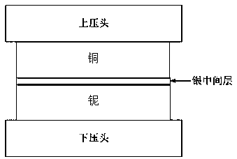
[0023] A copper plate with a thickness of 8 mm and a niobium plate with a thickness of 1 mm are used as connecting materials, and a silver foil with a thickness of 100 μm is used as an intermediate layer. Use 1000#, 1200#, 1500# SiC sandpaper to polish the surface to be connected of the copper plate and the niobium plate in turn until the surface roughness is 3 μm. Put it in acetone for ultrasonic cleaning for 10min, take it out and air dry. Assemble together from top to bottom in the order of copper plate / silver foil / niobium plate. Put the workpieces to be connected into the heating furnace, and apply 10MPa axial pressure to the workpieces through the upper and lower pressure heads. Close the oven door and evacuate to 5 × 10 -3 Pa. Then heated to 750 ºC at a rate of 20 ºC / min, kept for 30 min, then heated to 850 ºC at a rate of 10 ºC / min, kept for 60 min, and finally cooled to room temperature at a rate of 5 ºC / min to obtain niobium-silver-copper Connectors, when the ben...

Embodiment 2

[0025] A copper plate with a thickness of 8 mm and a niobium plate with a thickness of 2 mm were used as connecting materials, and the surfaces to be connected of the copper plate and the niobium plate were polished with 1000#, 1200#, and 1500# SiC sandpaper in sequence until the surface roughness was 3 μm. Put it in acetone for ultrasonic cleaning for 10min, take it out and air dry. Silver particles with a thickness of 80 µm and an average particle diameter of 20 µm were spread between the copper plate and the niobium plate. Put the workpieces to be connected into the heating furnace, and apply 25MPa axial pressure to the workpieces through the upper and lower pressure heads. Close the oven door and evacuate to 5 × 10 -3 Pa. Then heated at a rate of 20 ºC / min to 750 ºC, kept for 40 min, then heated to 850 ºC at a rate of 10 ºC / min, kept for 60 min, and finally cooled to room temperature at a rate of 10 ºC / min to obtain niobium-silver-copper Connectors, when the bending ang...

Embodiment 3

[0027] A copper plate with a thickness of 8 mm and a niobium plate with a thickness of 1 mm were used as connection materials, and the surfaces to be connected of the copper plate and the niobium plate were polished with 1000#, 1200#, and 1500# SiC sandpaper in sequence until the surface roughness was 2 μm. Put it in acetone for ultrasonic cleaning for 10min, take it out and air dry. Using magnetron sputtering technology, 20 μm and 20 μm silver layers were deposited on the surfaces of the copper and niobium plates to be connected, respectively. Assemble together from top to bottom according to the sequence of copper plate (silver plated surface) / (silver plated surface) niobium plate. Put the workpieces to be connected into the heating furnace, and apply 20MPa axial pressure to the workpieces through the upper and lower pressure heads. Close the furnace door and evacuate to 3 × 10⁻³ Pa. Then heated to 750 ºC at a rate of 15 ºC / min, kept for 50 min, then heated to 850 ºC at a ...


PUM

PropertyMeasurementUnit
thicknessaaaaaaaaaa
surface roughnessaaaaaaaaaa
thermal conductivityaaaaaaaaaa

Abstract

The invention relates to the technical field of copper niobium superconducting cavity making, in particular to a copper and niobium connector and a connecting method thereof. The copper and niobium connector is characterized in that the connector is composed of a copper plate, a silver intermediate layer and a niobium plate, and the upper and lower ends of the silver intermediate layer are connected with the copper plate and the niobium plate correspondingly. The connecting method includes the following steps that firstly, the to-be-connected surfaces of the niobium plate and the copper plateare ground to obtain the fresh metal surfaces, and acetone or ethyl alcohol are used for ultrasonic cleaning; secondly, metallic silver which can react eutectically with copper and form a solid solution with niobium is selected as the intermediate layer; and thirdly, the niobium plate, the silver intermediate layer and the copper plate are assembled together and put into a heating furnace, the mixture is pressurized, vacuumized and then heated for connection, and niobium silver copper connector is obtained after cooling and removing. The copper and niobium connector and the connecting method thereof have the advantages that the method is simple, the silver is used as the intermediate layer to connect the copper and the niobium, connection at the low temperature is realized, and good strength and deformation ability of a joint are ensured.

Description

technical field [0001] The invention relates to the technical field of manufacturing copper-niobium superconducting cavities, in particular to a copper-niobium connection using silver as an intermediate layer to realize connection at a relatively low temperature and ensure that the joint has good strength and deformability. Niobium connectors and connection methods. Background technique [0002] As we all know, metal niobium has excellent low-temperature superconductivity and is the key component material in superconducting acceleration chambers. However, niobium is expensive and has a low thermal conductivity of only 53.7 W / (m·K). The working state of the cavity needs to be combined with copper (386 W / (m K)) with high thermal conductivity, and the copper-niobium cavity has attracted more and more attention. [0003] At present, the existing literature "Development and preliminary experiments of copper-niobium sputtering low-β superconducting cavity, Hao Jiankui, Zhao Kui, ...

Claims


Application Information

Patent Timeline
Patent Type & Authority Applications(China)
IPC IPC(8): B23K20/02B23K20/16B23K20/24
CPCB23K20/02B23K20/023B23K20/16B23K20/24
Inventor 胡胜鹏付伟李绵绵宋晓国卞红冯吉才
Owner HARBIN INST OF TECH AT WEIHAI
Why Eureka
Try Eureka