Object and method for simulating and detecting pressure in penetration fusion welding small hole

A deep penetration welding and internal pressure technology, applied in welding equipment, welding equipment, laser welding equipment, etc., can solve the problems that need to be deepened, the correctness of simulation and calculation results cannot be verified by experimental means, and there is no internal pressure in the hole. problems, to achieve the effect of deepening understanding

Active Publication Date: 2019-04-16
HUNAN UNIV
View PDF4 Cites 5 Cited by
  • Summary
  • Abstract
  • Description
  • Claims
  • Application Information

AI Technical Summary

Problems solved by technology

However, this method has a significant disadvantage: the metal film layer used for welding is a loose structure, which is very different from the actual situation of the dense workpiece used for welding, because the loose multi-layer aluminum film has a deep impact on the laser. The influence of heat transfer, mass transfer and laser energy absorption and transmission process in the fusion welding process is very different from the dense aluminum alloy materials used in engineering practice. The actual situation of the material is very different
[0012] To sum up, it can be seen that the research on the pressure in the small hole of deep penetration welding is currently mainly limited to the theoretical research carried out by simulation or calculation methods. The correctness of the calculated results cannot be verified by experimental means
Therefore, the research on the role of the pressure balance in the pores in the formation and maintenance of the pores and the relationship between the pressure in the pores and the shape of the pores remains to be done.

Method used


Image

  • Object and method for simulating and detecting pressure in penetration fusion welding small hole
  • Object and method for simulating and detecting pressure in penetration fusion welding small hole
  • Object and method for simulating and detecting pressure in penetration fusion welding small hole

Examples


Embodiment 1

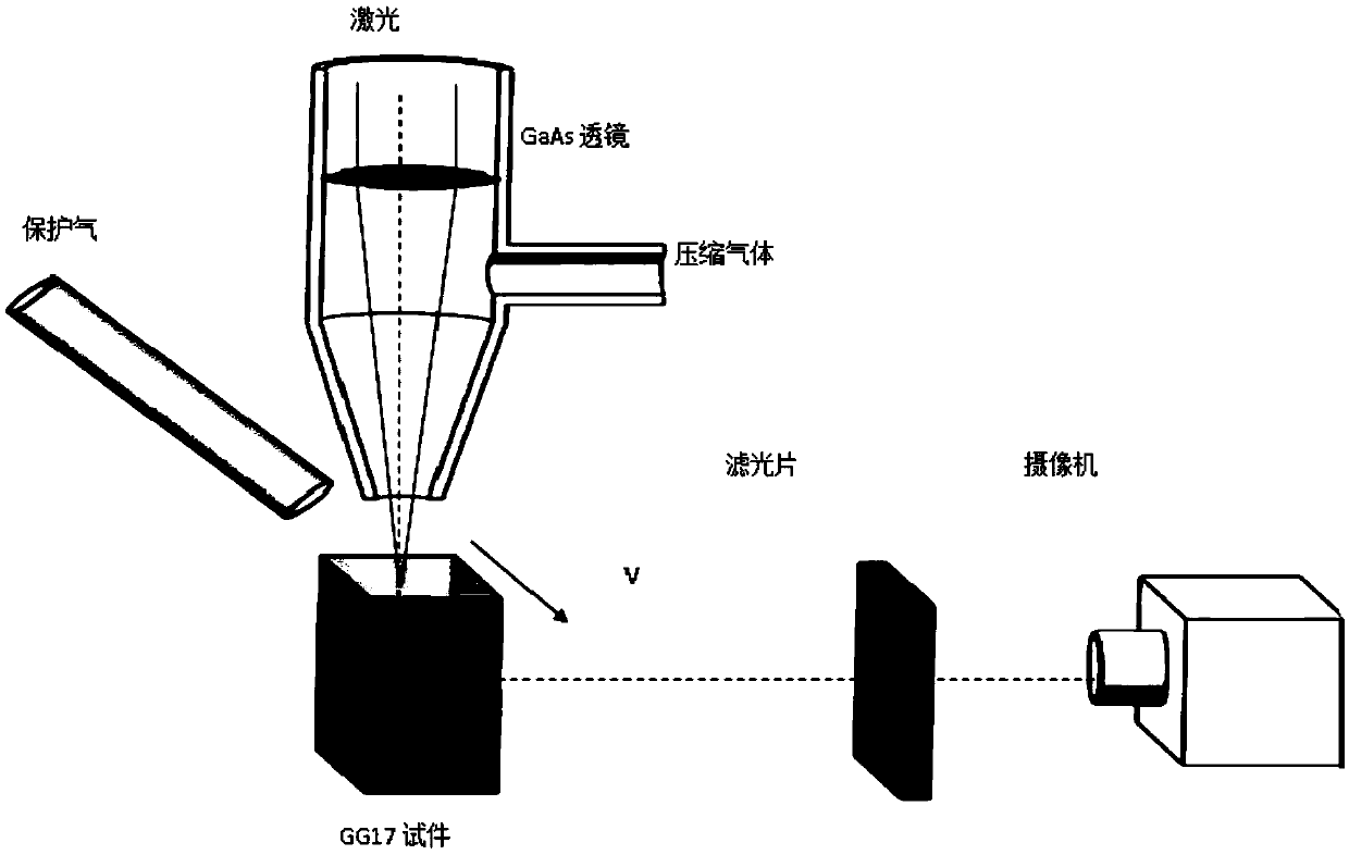
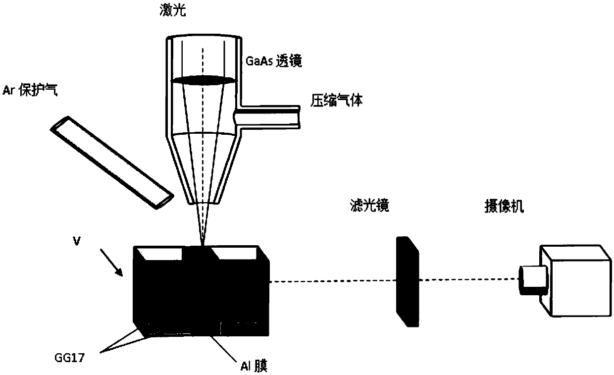
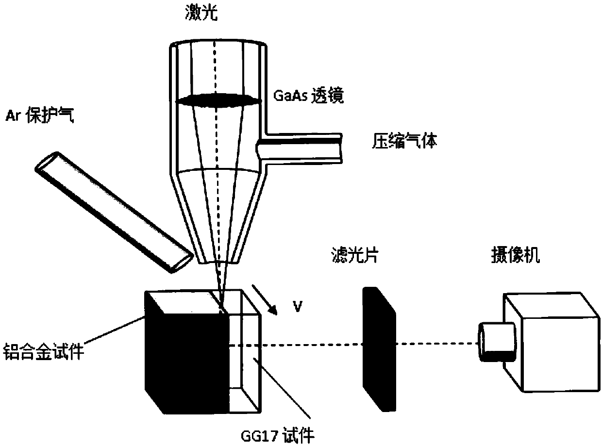
[0053] This embodiment provides as Image 6 The omnidirectional direct observation device for the shape of the small hole in the deep penetration welding of the metal material, and the use of such as Image 6 The device shown is a technical solution for directly observing the cross-sectional contour shape of small holes at different depths in layers.

[0054]The all-round direct observation device for the shape of small holes in deep penetration welding of metal materials includes a welding head, a composite test piece located under the welding head, and an image capturing component for observing the shape of small holes; the welding head is capable of using laser or electronic The welding head of the beam; the composite test piece includes the upper metal part 4 and the lower GG17 part 5, and the top surface of the whole composite test piece, that is, the top surface of the metal part, is a plane, and the bottom surface of the metal part and the top surface of the GG17 part ...

Embodiment 2

[0071] This embodiment provides as Figure 5 The object and device for simulating and detecting the pressure in the small hole of deep penetration welding, and the method for simulating and detecting the pressure in the small hole of deep penetration welding.

[0072] The high-pressure gas is sprayed onto the surface of the experimental liquid 22 along the side wall of the liquid container 24 through the high-pressure gas spray head 15 to form a simulated small hole 17 in the liquid. The high-pressure gas passes through the spray head 15 and the liquid container 24 has relative motion. The gas pressure is detected by the pressure gauge 16. The high-speed camera, that is, the first camera 18, shoots the appearance of the longitudinal symmetrical plane of the simulated small hole through the transparent side wall of the liquid container 24. The high-speed camera, that is, the second camera 20, shoots the liquid through the support 21. Simulated pinhole topography on the bottom ...


PUM


Abstract

The invention provides an object and method for simulating and detecting the pressure in a penetration fusion welding small hole. The object comprises an upper liquid container and a lower supportingpiece; the liquid container comprises one or more vertical side plates, the side plates are flat plates and are each made of transparent glass, and a bottom plate of the liquid container is made of transparent glass; a top plate of the supporting piece is vacant or is made of transparent glass, when the bottom face of the whole object, namely the bottom face of the supporting piece is horizontallyarranged, the inner bottom face, namely the liquid bottom face of the liquid container is a flat face, and an included angle theta is formed between the inner bottom face and the horizontal plane, wherein theta is larger than 0 degree and smaller than 90 degrees; and the object further comprises experimental liquid which is added into the liquid container and used for simulating molten metal during penetration fusion welding. According to the object and method for simulating and detecting the pressure in the penetration fusion welding small hole, a good and feasible way is provided for thoroughly solving the problem of direct detection of the pressure in the penetration fusion welding small hole, and great convenience is brought to researching of the relation between the hole interior pressure of the penetration fusion welding small hole and the shape of the small hole.

Description

technical field [0001] The invention relates to the field of deep penetration welding, in particular to an object and method for simulating and detecting the pressure in a small hole of deep penetration welding. Background technique [0002] As a high-quality and efficient welding method, deep penetration welding (including laser, electron beam, etc.) has the advantages of fast welding speed, large weld depth-to-width ratio, small heat-affected zone and welding deformation, and is widely used in steel, nuclear power, aerospace, etc. It has been more and more widely used in military and civil major projects such as railway transportation, automobile, electronics industry, etc., especially in the lightweight of transportation vehicles (welding of thin-walled objects and lightweight materials such as aluminum and magnesium alloys). play an increasingly important role. [0003] 1. Current status of pinhole observation technology [0004] The essential feature of deep penetrati...

Claims


Application Information

Patent Timeline
Patent Type & Authority Applications(China)
IPC IPC(8): B23K37/00B23K15/00B23K26/03B23K26/70
CPCB23K15/00B23K15/0013B23K26/03B23K26/70B23K26/702B23K37/00
Inventor 金湘中蒋志伟周昕宇
Owner HUNAN UNIV
Why Eureka
Try Eureka