Intelligent control system of water heater

An intelligent control system and water heater technology, applied in the direction of combustion control, fluid heater, fuel supply adjustment, etc., can solve the problems of inability to do intelligent combustion oxygen supply and water supply and discharge operations, affecting the working environment of operators, and air pollution and other issues to achieve the effect of reducing emissions, improving the working environment, and improving intelligence

Inactive Publication Date: 2019-04-16
SIYUAN ELECTRIC APPLIANCES
View PDF5 Cites 0 Cited by
  • Summary
  • Abstract
  • Description
  • Claims
  • Application Information

AI Technical Summary

Problems solved by technology

[0003] The purpose of the present invention is to provide an intelligent control system for water heaters, so as to solve the problem that the existing water heaters proposed in the above-mentioned background technology cannot perform intelligent combustion and oxygen supply and water supply and discharge operations during heating and utilization, and do not treat exhaust gas discharge. Operation, not only affects the working environment of operators, but also causes serious pollution to the atmosphere

Method used


Image

  • Intelligent control system of water heater
  • Intelligent control system of water heater
  • Intelligent control system of water heater

Examples


Embodiment 1

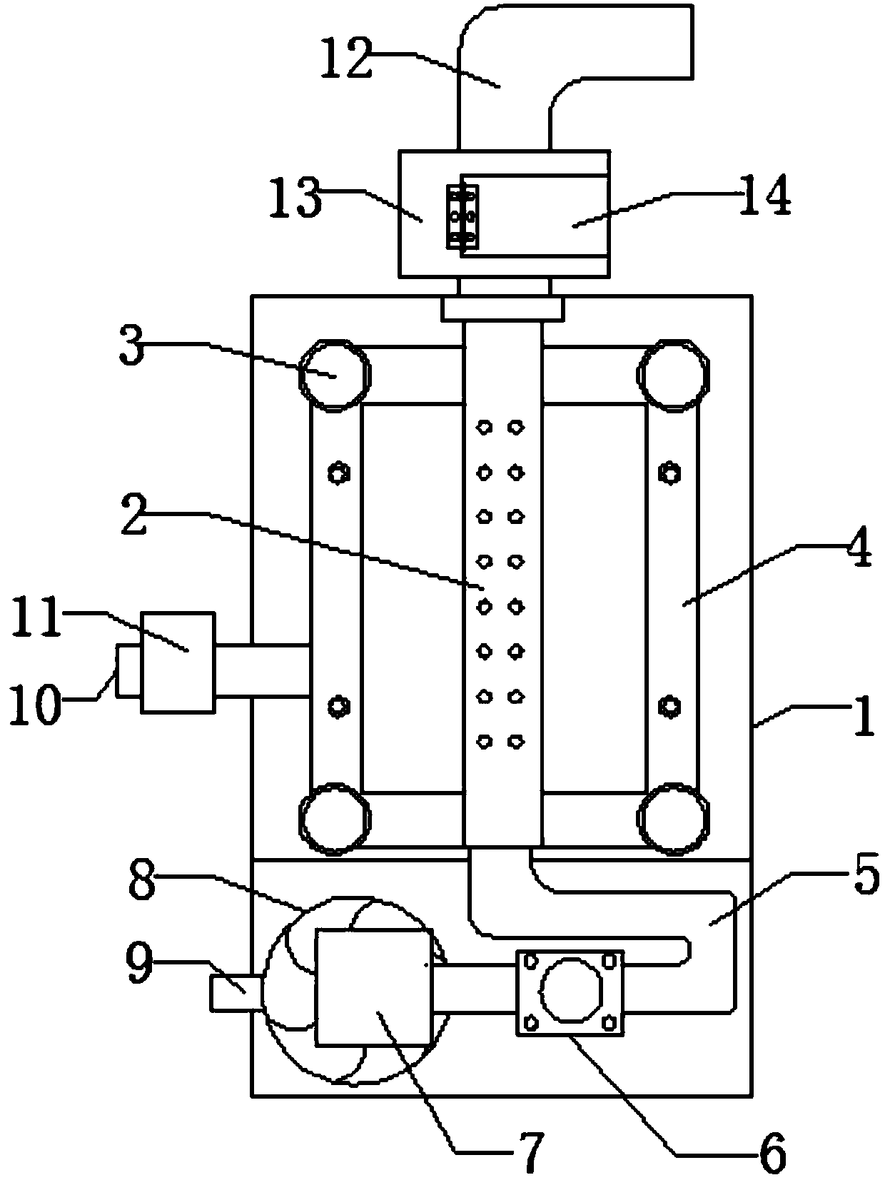
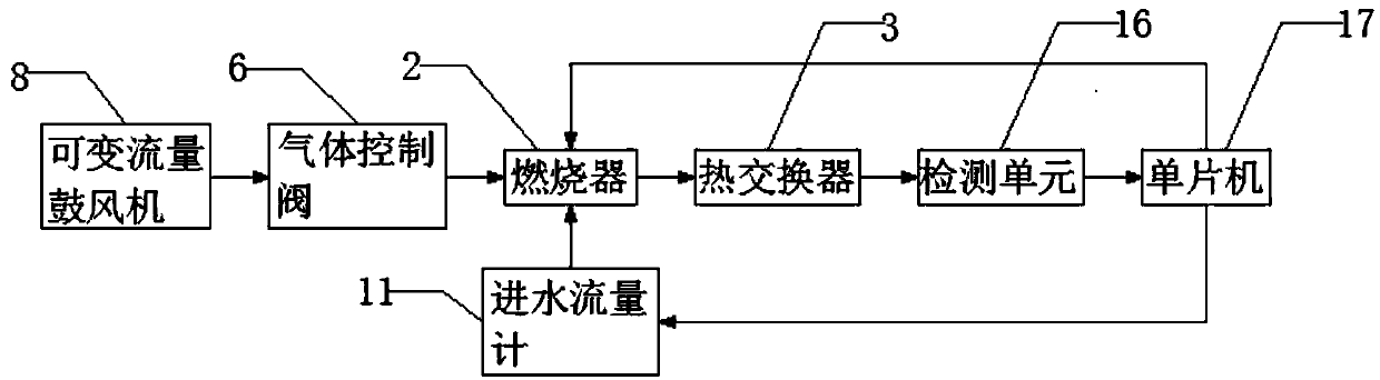
[0021] see Figure 1-3 , this embodiment provides an intelligent control system for a water heater, including a device body 1, a burner 2 is fixedly installed in the middle of the device body 1, a heat exchanger 3 is fixedly installed outside the burner 2, and a gas Supply pipe 5, one end of the gas supply pipe 5 is fixedly installed with a gas control valve 6, the input end of the gas control valve 6 is fixedly connected with a Venturi tube 7 through the gas supply pipe 5, and the other end of the Venturi tube 7 is fixedly installed with a variable flow blower 8 , the input end of the variable flow blower 8 is fixedly connected with the intake pipe 9, the left side of the device body 1 is fixedly connected with the water inlet pipe 10, the water inlet flowmeter 11 is installed on the water inlet pipe 10, and the upper end of the burner 2 is fixedly connected with the waste gas pipeline 12, A purification cartridge 13 is fixedly connected to the waste gas pipeline 12 , a detec...

Embodiment 2

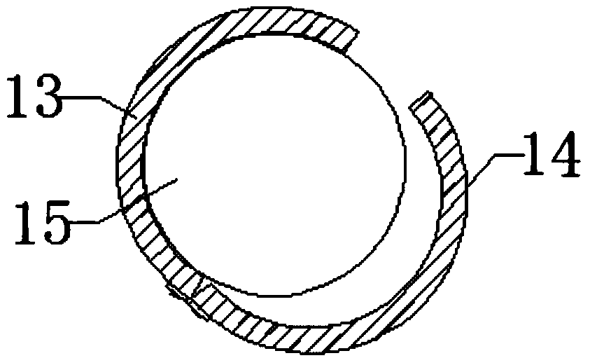
[0024] see Figure 1-3 , on the basis of Example 1, a further improvement has been made: finned tubes 4 are arranged on both sides of the heat exchanger 3, which can increase the outer surface area of ​​the heat exchange tubes, thereby achieving the purpose of improving heat exchange efficiency, and the side of the purification cylinder 13 passes through The hinge is rotatably connected with a sealed door 14, and the sealed door 14 is fixedly connected with a filter sheet 15. The filter sheet 15 can be replaced regularly through the sealed door 14, which is convenient for use. The filter sheet 15 is a filter material purification sheet, which is harmful to the filter The gas effect is better. The exhaust gas pipeline 12 is made of high molecular polymer material, which has good heat resistance and corrosion resistance. The input signal of the water inlet flow meter 11 is the flow rate signal from the water inlet pipe 10. The structure is reasonable and easy to detect. , the ex...


PUM


Abstract

The invention discloses an intelligent control system of a water heater. The intelligent control system comprises a device body. A combustor is fixedly installed on the middle portion of the device body. A heat exchanger is fixedly installed on the outer side of the combustor. A gas supply pipe is fixedly connected to the lower end of the combustor. A gas control valve is fixedly installed at oneend of the gas supply pipe. The input end of the gas control valve is fixedly connected with a venturi pipe through the gas supply pipe. A variable flow air blower is fixedly installed at the other end of the venturi pipe. The input end of the variable flow air blower is fixedly connected with a gas input pipe. A waste gas pipeline is fixedly connected to the upper end of the combustor. A purifying cylinder is fixedly connected into the waste gas pipeline. According to the intelligent control system, use intelligence of the intelligent control system of the water heater is improved, it is ensured that in heating utilization process, intelligent combustion oxygen supply and water feeding and draining operation of the water heater can be achieved, the waste gas is sucked and treated, the working environment of operators is improved, and emissions of atmospheric pollutants are reduced.

Description

technical field [0001] The invention relates to the technical field of water heater equipment, in particular to an intelligent control system for a water heater. Background technique [0002] Water heaters have become household appliances that people use every day. In order to meet the water needs of users in different scenarios, water heaters often design different water consumption modes in different scenarios. Traditional water heater technology utilizes a burner designed to run a fixed flow rate of combustion air and fuel gas to the burner. Such water heaters are turned on and off in response to a control system that monitors the temperature of the water in the storage tank or elsewhere in the various pipes of the water supply system. Therefore, the existing water heaters cannot perform intelligent combustion and oxygen supply and water supply and discharge operations during heating and utilization, and have not processed exhaust gas emissions, which not only affects t...

Claims


Application Information

Patent Timeline
Patent Type & Authority Applications(China)
IPC IPC(8): F24H9/20F23N1/02
CPCF23N1/025F23N2225/08F23N2233/08F23N2235/12F24H9/2035
Inventor 徐宁向熹
Owner SIYUAN ELECTRIC APPLIANCES
Why Eureka
Try Eureka