Electromagnetic driving galvanometer and driving magnetic circuit thereof

An electromagnetic drive, magnetic circuit technology, applied in electrical components, electromechanical devices, optics, etc., can solve problems such as reducing volume, and achieve the effects of reducing stress concentration, high energy utilization, and low energy loss

Pending Publication Date: 2019-04-16
XI AN ZHISENSOR TECH CO LTD
View PDF9 Cites 5 Cited by
  • Summary
  • Abstract
  • Description
  • Claims
  • Application Information

AI Technical Summary

Problems solved by technology

[0003] Magnetic flux leakage is inevitable in electromagnetic drive. If the oscillating mirror achieves the target rotation angle, and t

Method used


Image

  • Electromagnetic driving galvanometer and driving magnetic circuit thereof
  • Electromagnetic driving galvanometer and driving magnetic circuit thereof
  • Electromagnetic driving galvanometer and driving magnetic circuit thereof

Examples


Embodiment 1

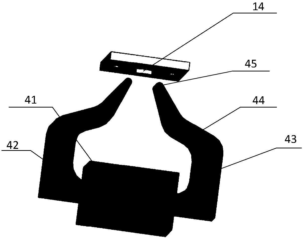
[0030] From figure 1 It can be seen that the drive magnetic circuit 34 of this embodiment includes a crab-claw iron core, and the iron core material can be pure iron with high permeability, low carbon steel, iron-nickel alloy, ferrosilicon alloy, ferrite and other materials.

[0031] The iron core includes a core part 42 and an iron yoke part. A coil 41 with a certain number of turns is wound around the core part 42, and a changing current is passed to the coil 41 to generate a changing magnetic field. The core permeability is much higher than that of air. The catharsis will concentrate on the iron core. The iron yoke part is composed of the first iron yoke part 43, the second iron yoke part 44 and the open end 45, which is used to guide the magnetic circuit to the vicinity of the magnetic material used as the galvanometer drive. The core column part 42 can be a simple strip shape, an arc shape or other linear shapes. The length of this part is ensured to prevent the thickness of ...

Embodiment 2

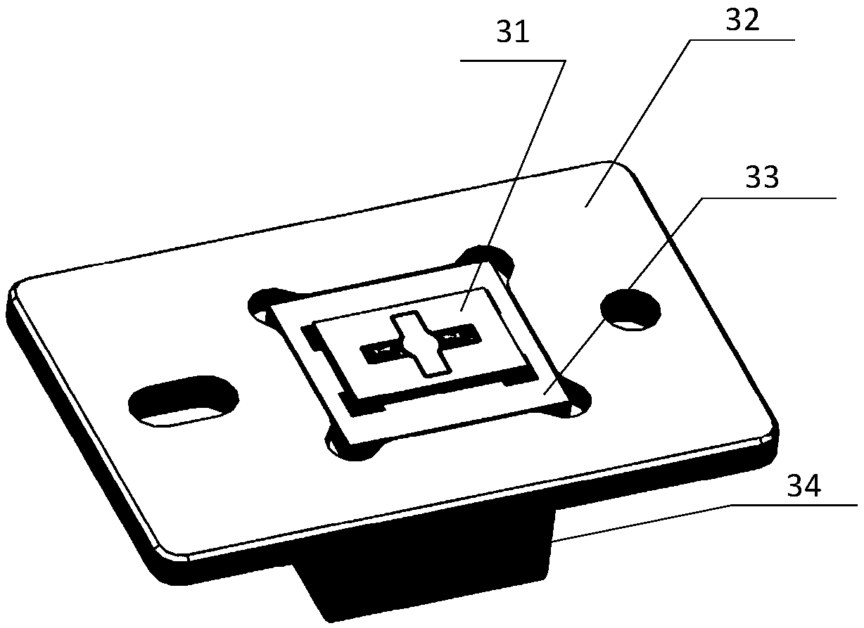
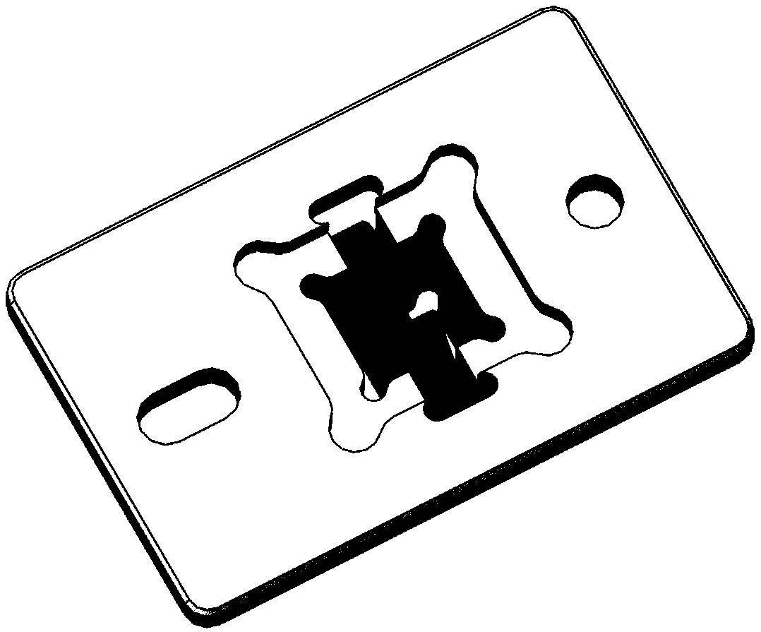
[0035] From figure 2 It can be seen that the electromagnetic drive galvanometer in this embodiment mainly includes an electromagnetic galvanometer chip 31, a structure body 32 and a drive magnetic circuit 34. The structure 32 supports and fixes the electromagnetic galvanometer chip 31 and the drive magnetic circuit 32, combines the electromagnetic galvanometer chip 31 and the drive magnetic circuit 32 together, and ensures the relative position of the two, and provides an external interface for the electromagnetic drive galvanometer (Including mechanical interfaces or fixed electrical components or interfaces).

[0036] The electromagnetic galvanometer chip 31 in this embodiment includes a movable mirror 11, a torsion beam 12 and a fixed frame 13, and the movable mirror 11 is fixed on the fixed frame 13 by the torsion beam 12. The reverse side of the movable mirror 11 is provided with a magnetic material 14 and reinforcing ribs. When the inertial deformation of the movable mirro...

Embodiment 3

[0039] Due to different materials and different thermal expansion coefficients between the electromagnetic galvanometer chip 31 and the structural body 32, the galvanometer structure will generate stress when the system working environment temperature changes, which will cause changes in the galvanometer performance such as resonant frequency. figure 2 It can be seen that in this embodiment, on the basis of the second embodiment, a stress buffer structure 33 is provided between the electromagnetic galvanometer chip 31 and the structure body 32. The stress buffer structure 33 can be positioned and fixed to the structure body 32, and the electromagnetic galvanometer chip 31 can be positioned and fixed to the stress buffer structure 33; the difference between the electromagnetic galvanometer chip 31 and the structure body 32 caused by different materials The thermal stress problem caused by different thermal expansion coefficients. The material of the stress buffer structure 33 sho...


PUM


Abstract

The invention belongs to the field of micro-optical machine electricity, and specifically relates to an electromagnetic driving galvanometer and a driving magnetic circuit thereof. The driving magnetic circuit comprises a coil and an iron core. The iron core is shaped like a crab claw and comprises an iron yoke part and a stem part. The coil is wound on the stem part. The iron yoke part comprisesa first iron yoke part, a second iron yoke part and an open end, wherein the first iron yoke part, the second iron yoke part and the open end are integrally arranged in order. The first iron yoke partand the stem part are integrally arranged. The cross-sectional areas of the first iron yoke part, the second iron yoke part and the open end vary from large to small. The magnetic field of an electromagnet is concentrated on a permanent magnet to the greatest extent, which has the advantages of less energy loss and high energy utilization.

Description

Technical field [0001] The invention belongs to the field of micro-opto-electromechanics, in particular an electromagnetic drive galvanometer and its drive magnetic circuit. Background technique [0002] Compared with traditional beam deflecting components, MEMS galvanometer has the advantages of miniaturization, low energy consumption, fast response, easy integration, and long life. With the development of artificial intelligence and the demand for high precision, miniaturization and low cost of devices, MEMS Galvo mirrors shine in three-color laser projection, lidar, 3D measurement and other fields. Among them, electromagnetic drive has the advantages of linear response, large driving force, fast response speed, low driving voltage, and insensitivity to size. It is one of the most commonly used driving methods for micro galvanometers. Electromagnetically driven torsion mirrors can be divided into two types from the source of magnetic force: Lorentz force drive and electromagne...

Claims


Application Information

Patent Timeline
IPC IPC(8): G02B26/08H02K33/00
CPCG02B26/085H02K33/00
Inventor 宋秀敏夏长锋惠凯乔大勇何伟
Owner XI AN ZHISENSOR TECH CO LTD
Why Eureka
Try Eureka