Duplexer

A duplexer and resonator technology, which is applied in the field of semiconductors and micro-electromechanical systems, can solve the problems of limiting the overall performance of the filter, difficult to guarantee the performance of the resonator, and limited adjustable range, etc., to achieve out-of-band suppression and isolation improvement , wide adjustment range, improve the effect of in-band insertion loss

Active Publication Date: 2019-04-16
TIANJIN UNIV +1
View PDF18 Cites 6 Cited by
  • Summary
  • Abstract
  • Description
  • Claims
  • Application Information

AI Technical Summary

Problems solved by technology

However, the frequency of the resonator in the FBAR filter is achieved by adjusting the thickness of the physical layer, the adjustable range is limited, and the performance of the resonator is difficult to guarantee when the adjustment range is too wide
In addition, the piezoelectric coupling coe...

Method used


Image

  • Duplexer
  • Duplexer
  • Duplexer

Examples


Embodiment 1

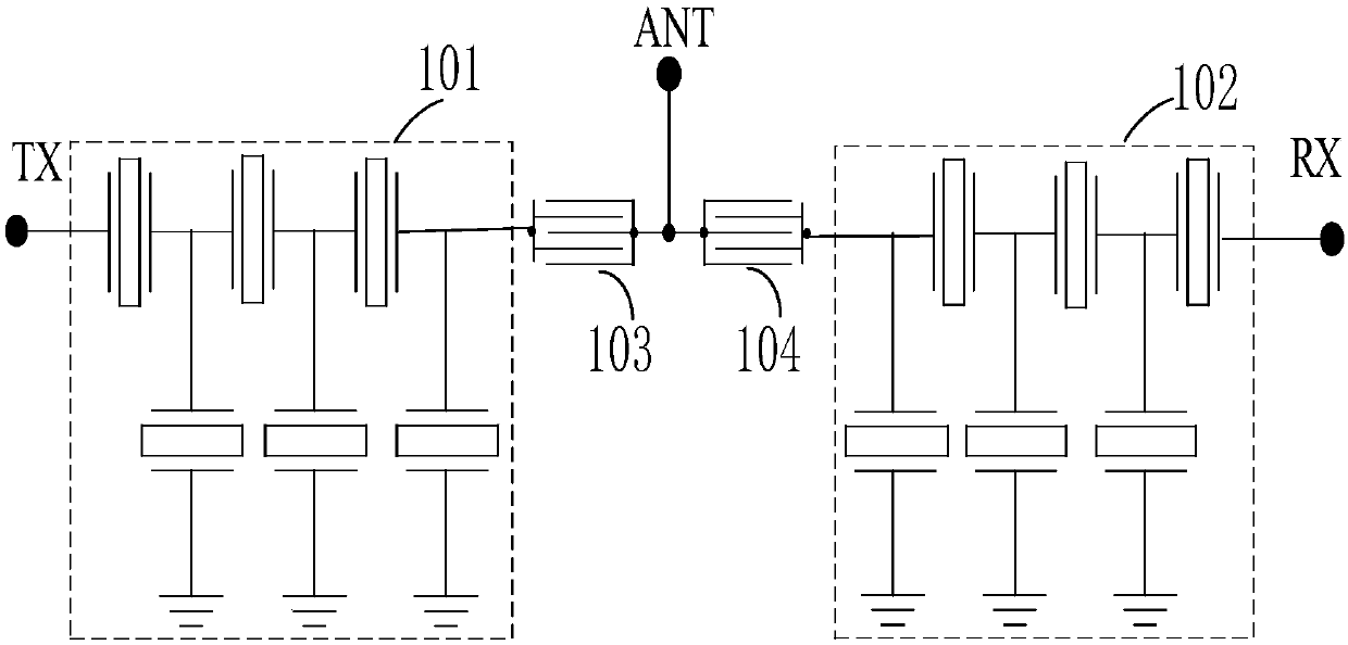
[0049] figure 1 A circuit structure diagram of the duplexer according to the first embodiment of the present application is shown. Such as figure 1 As shown, a duplexer includes:

[0050] a transmit filter 101 connected between a transmit terminal (TX) and an antenna terminal (ANT) and including series resonators and parallel resonators connected in a trapezoidal form; and

[0051] a receiving filter 102 connected between a receiving terminal (RX) and the antenna terminal (ANT) and comprising series resonators and parallel resonators connected in a trapezoidal form,

[0052] Among them, the LWR resonator is two groups, one group of transmitting end series LWR resonator 103 is connected in series between the transmitting filter 101 and the antenna end (ANT), and another group of receiving end series LWR resonator 104 is connected in series between the receiving filter 102 and the antenna end (ANT). between the antenna terminals (ANT).

[0053]Specifically, both the transmit...

Embodiment 2

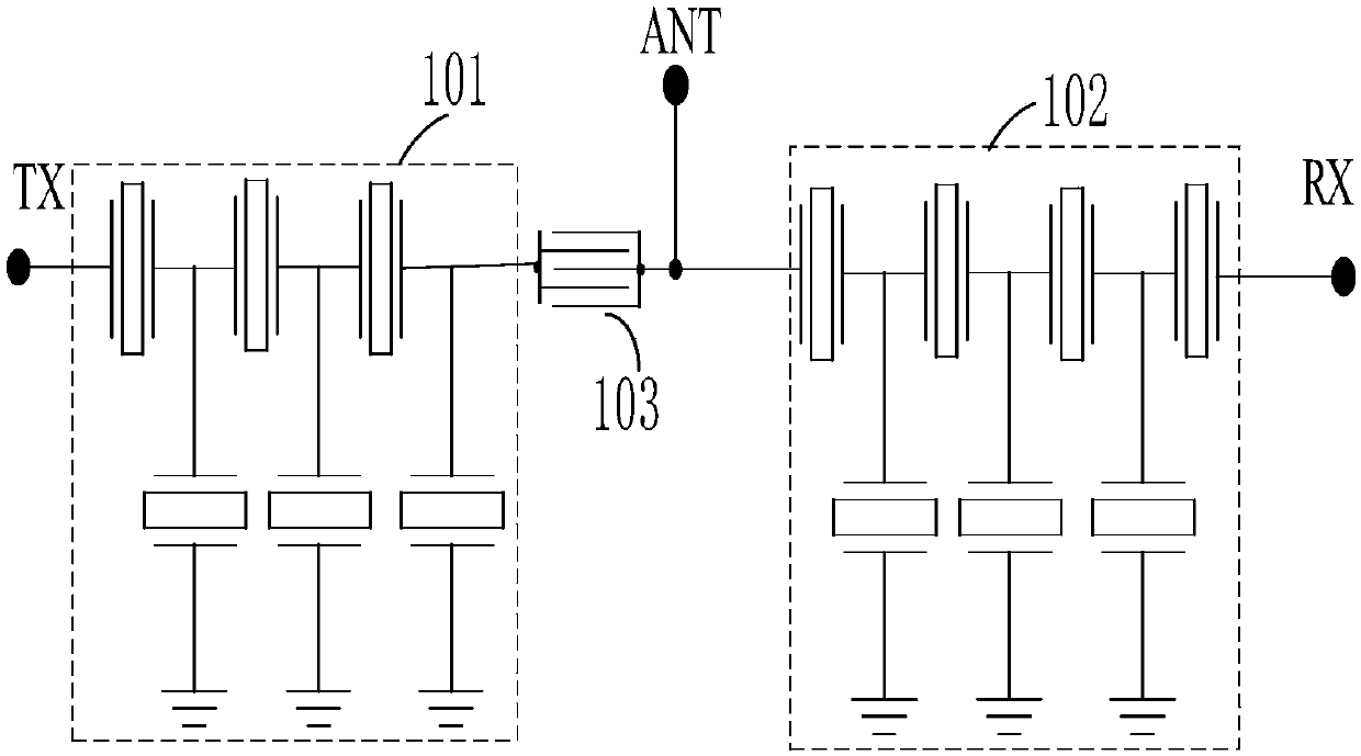
[0065] Figure 4 A circuit structure diagram of a duplexer according to the second embodiment of the present application is shown. Such as Figure 4 As shown, a duplexer includes:

[0066] a transmit filter 101 connected between a transmit terminal (TX) and an antenna terminal (ANT) and including series resonators and parallel resonators connected in a trapezoidal form; and

[0067] a receiving filter 102 connected between a receiving terminal (RX) and the antenna terminal (ANT) and comprising series resonators and parallel resonators connected in a trapezoidal form,

[0068] There are two groups of LWR resonators, and the two groups of LWR resonators 105 and 106 are respectively connected to the parallel branch of any node in the transmitting filter 101 and receiving filter 102 and connected to the ground terminal.

[0069] Specifically, the transmitting filter 101 and the receiving filter 102 are both composed of four-stage series resonators and two-stage parallel resonat...

Embodiment 3

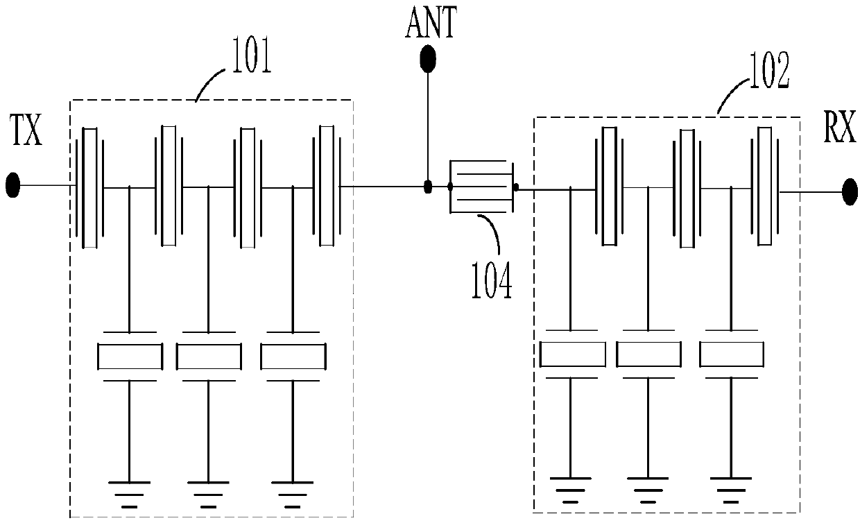
[0081] Figure 7 A circuit structure diagram of a duplexer according to the third embodiment of the present application is shown. Such as Figure 7 As shown, a duplexer includes:

[0082] a transmit filter 101 connected between a transmit terminal (TX) and an antenna terminal (ANT) and including series resonators and parallel resonators connected in a trapezoidal form; and

[0083] a receiving filter 102 connected between a receiving terminal (RX) and the antenna terminal (ANT) and comprising series resonators and parallel resonators connected in a trapezoidal form,

[0084] Wherein, there are four groups of LWR resonators, a group of transmitting end series LWR resonators 103 are connected in series between the transmitting filter 101 and the antenna end (ANT), and a group of receiving end series LWR resonators 104 are connected in series between the receiving filter 102 and the antenna. Between terminals (ANT), a group of parallel LWR resonators 105 at the transmitting en...


PUM


Abstract

The invention provides a duplexer. The duplexer comprises a transmitting filter, wherein the transmitting filter is connected between a transmitting end and an antenna end and comprises a series resonator and a parallel resonator connected in a trapezoidal form; and a receiving filter, wherein the receiving filter is connected between a receiving end and the antenna end and comprises a series resonator and a parallel resonator connected in a trapezoidal form, wherein an LWR resonator is connected to a series branch of the TX (transmitting end) or the RX (receiving end), or the LWR resonator isconnected to a parallel branch of the TX or the RX and is connected with a grounding end. According to the duplexer provided by the invention, the LWR resonator is introduced into the structural design of the filter and the duplexer, and is applied to the structure of a piezoelectric filter and the duplexer to improve the performance of the piezoelectric filter and the duplexer; the characteristics of the impedance characteristic, the flexible frequency and piezoelectric coupling coefficient adjustment of an LWR resonant frequency point are utilized, a combination of different frequencies andpiezoelectric coupling coefficients is adopted, and required impedance conversion is realized at a specific frequency point.

Description

technical field [0001] The invention relates to the field of semiconductors and micro-electromechanical systems, in particular to a duplexer. Background technique [0002] With the rapid development of wireless communication systems, the performance requirements of the RF front-end are becoming more and more stringent. Moreover, the wireless communication system is developing towards the direction of multi-function, multi-band, and multi-protocol, which poses a higher challenge to the RF front-end in wireless communication equipment. As a very important module in the RF front-end, the performance of the filter duplexer plays a decisive role in the performance of the RF front-end. Therefore, there is a very urgent need to continuously improve the performance of the filter duplexer. [0003] In the field of radio frequency communication, Film Bulk Acoustic Wave Resonator (FBAR) has attracted more and more attention due to its small size, high roll-off, and low insertion loss...

Claims


Application Information

Patent Timeline
IPC IPC(8): H03H9/70H03H9/15H03H9/205H03H9/02
CPCH03H9/02236H03H9/02244H03H9/15H03H9/205H03H9/70H03H2009/155H03H2009/02251
Inventor 庞慰蔡华林
Owner TIANJIN UNIV
Why Eureka
Try Eureka