Pulling method of array optical fiber optical tweezers

A technology of array optical fiber and manufacturing method, which is applied in the direction of optics, light guides, optical components, etc., can solve the problems of loose fiber arrangement, inconsistent fiber taper angle, and affecting the use of optical tweezers, so as to achieve complete stripping, improve efficiency, and shorten adjustment time. Effect

Active Publication Date: 2019-04-23
NO 34 RES INST OF CHINA ELECTRONICS TECH GRP
View PDF15 Cites 0 Cited by
  • Summary
  • Abstract
  • Description
  • Claims
  • Application Information

AI Technical Summary

Problems solved by technology

[0006] The array fiber optical tweezers obtained by traditional glue or wire binding have disadvantages such as loose arrangement of optical fibers, partial bending, and inconsistent cone angles between optical fibers, which affect the use of optical tweezers.

Method used


Image

  • Pulling method of array optical fiber optical tweezers
  • Pulling method of array optical fiber optical tweezers
  • Pulling method of array optical fiber optical tweezers

Examples


Embodiment Construction

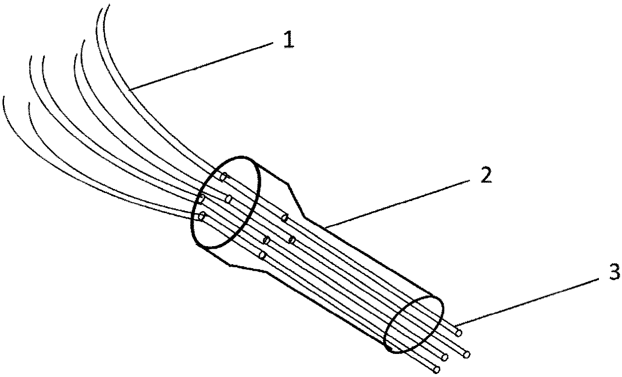
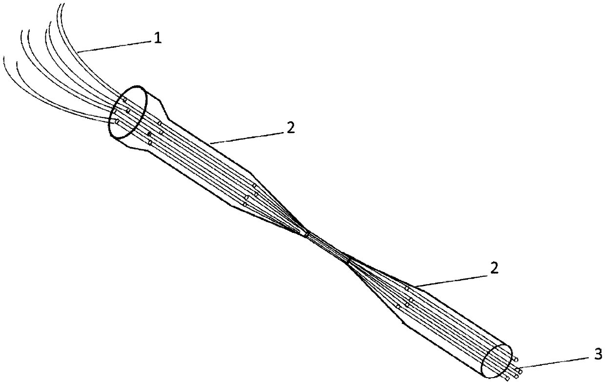
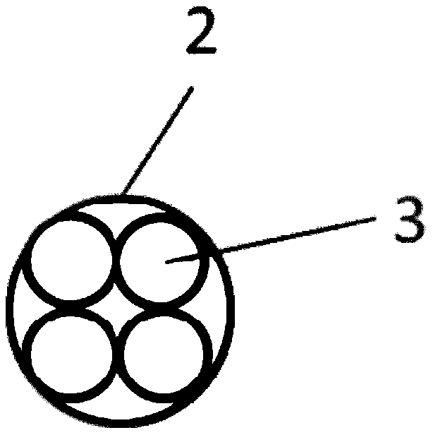
[0034] The embodiment of the drawing method of the array optical fiber optical tweezers is to draw a 4-core 2×2 array optical fiber optical tweezers.

[0035] A method for drawing an array optical fiber optical tweezers, comprising the following main steps:

[0036] Ⅰ. Removal of optical fiber coating

[0037] Take multiple optical fibers of the same specification, soak one end of each optical fiber with a length of 65 mm in concentrated sulfuric acid, and take out the optical fibers whose coating has been corroded for 20 to 30 minutes. Use ethanol and acetone solution to fully wipe the uncoated bare fiber, and observe the bare fiber part under a microscope to confirm that no scars are caused during the treatment process, and it will be used after drying.

[0038] The method of stripping the optical fiber coating layer by chemical solvent etching is superior to mechanical stripping and flame ablation stripping. Although mechanical stripping is easy to operate and implement, ...


PUM


Abstract

The invention relates to a pulling method of array optical fiber optical tweezers. A coating layer at one end of each optical fiber is removed, and bare optical fibers are threaded into a quartz tubein bundles; the quartz tube is fixed to a tapering clamp, the external moving velocity and the flame moving velocity of the tapering clamp is controlled to conduct test pulling, the insertion loss ofthe obtained array optical tweezers is detected, the flame sprayer nozzle height is adjusted, the heated temperature of the quartz tube is precisely controlled, the insertion loss meets the requirements, after the flame sprayer nozzle height and the flame moving velocity are determined, the external moving velocity of the tapering clamp is controlled to subjected to variable speed tapering from slow to fast, and the optical fiber tweezers with the taper angle of 30 degrees-45 degrees are obtained. According to the pulling method of the array optical fiber optical tweezers, the quartz tube perfectly constrains optical fiber bundles, optical fibers of the array optical fiber optical tweezers are closely arranged and symmetrical relative to the center line, and the efficiency is significantlyimproved; and the heated temperature of the quartz tube is adjusted through the flame sprayer nozzle height, the temperature adjustment accuracy is less than 0.5 DEG C, quick tapering at multiple variable speed ensures the index of the insertion loss of the array optical fiber optical tweezers is qualified, and the test pulling time is shortened.

Description

technical field [0001] The invention relates to the technical field of fabricating an array optical fiber optical tweezers, in particular to a drawing method of an array optical fiber optical tweezers. Background technique [0002] In 1969, Ashkin et al. of Bell Labs in the United States first realized laser-driven microparticles, and found that when the refractive index of the particles is greater than the refractive index of the surrounding medium, the particles will be sucked into the beam in the lateral direction, and two laser beams propagating in opposite directions are used. A double-beam optical trap is realized. In 1970, Ashkin et al. first proposed the concept of manipulating tiny particles using light pressure, and successfully clamped and moved small glass beads in aqueous solution using a two-dimensional potential well of a multi-beam laser. Later, the technology of this laser clamping particle was continuously improved. , the particle size that can be captured...

Claims


Application Information

Patent Timeline
Patent Type & Authority Applications(China)
IPC IPC(8): G02B6/255G21K1/00
CPCG02B6/2552G21K1/006
Inventor 吴国锋赵灏覃波刘志强童章伟阳华张昕鲁正
Owner NO 34 RES INST OF CHINA ELECTRONICS TECH GRP
Why Eureka
Try Eureka