Fuel-engine-driven compression-absorption combined type heat pump system

An engine-driven, heat pump system technology, used in fuel, heat pump and heating, thermal energy, power fields, can solve application limitations, performance impact and other issues

Inactive Publication Date: 2019-04-26
ZHEJIANG SCI-TECH UNIV
View PDF8 Cites 2 Cited by
  • Summary
  • Abstract
  • Description
  • Claims
  • Application Information

AI Technical Summary

Problems solved by technology

However, in severe cold regions, this method is still restricted by the characteristics of air source heat pumps, and the external temperature still has a certain impact on its performance. In severe cold regions, its application is still limited

Method used


Image

  • Fuel-engine-driven compression-absorption combined type heat pump system
  • Fuel-engine-driven compression-absorption combined type heat pump system
  • Fuel-engine-driven compression-absorption combined type heat pump system

Examples


Embodiment 1

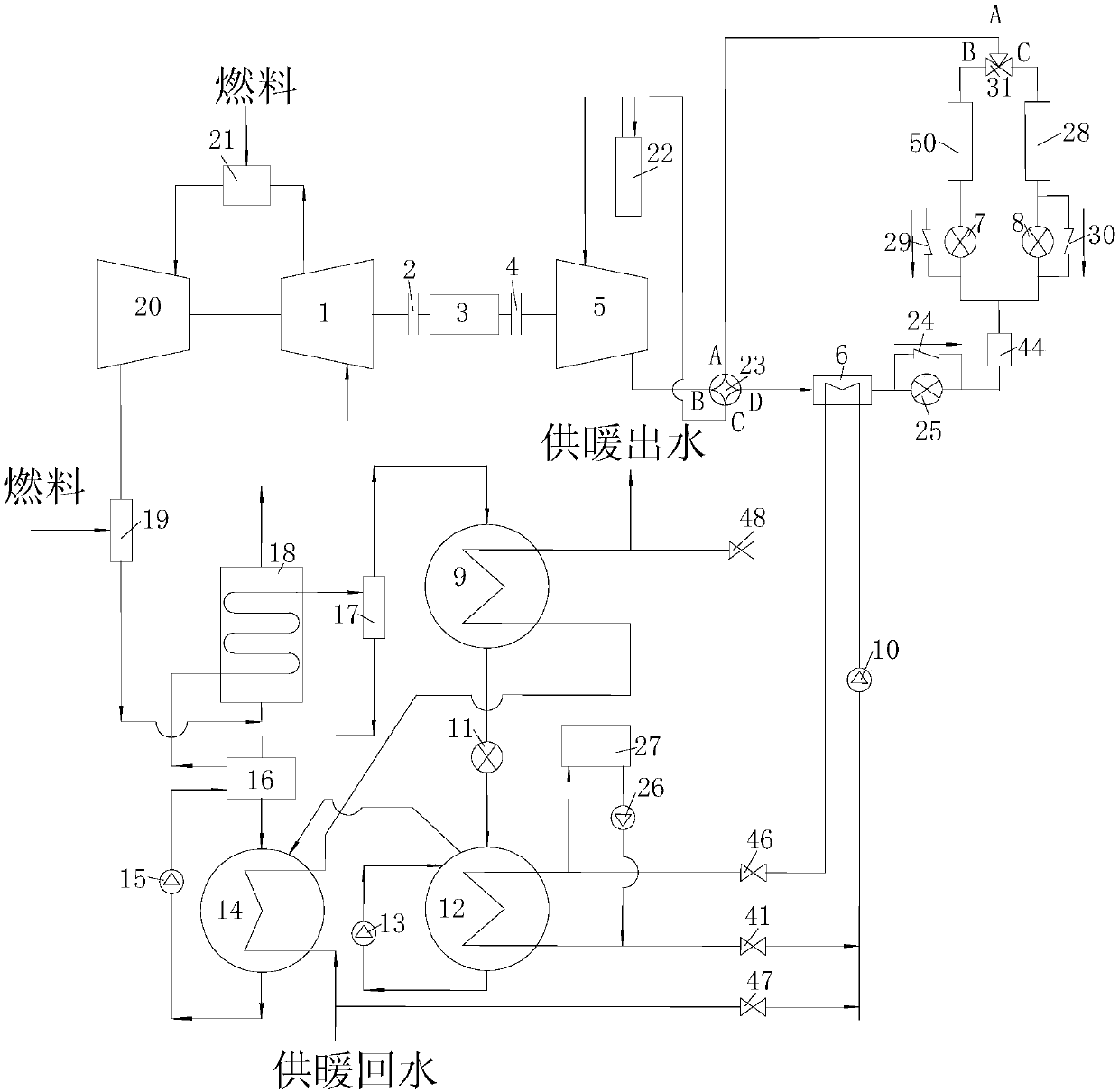
[0063] Embodiment 1. The compression-absorption composite heat pump system driven by the fuel engine of the present invention adopts the scheme 1 of a gas turbine, such as figure 1As shown, it includes compressor 1, clutch 2, clutch 4, coupling 3, compressor 5, condenser 6, condenser 9, evaporator 12, absorber 14, solution heat exchanger 16, gas-liquid separator 17 , generator 18, afterburning combustion chamber 19, turbine 20, combustion chamber 21, gas-liquid separator 22, four-way valve 23 and three-way valve 31.

[0064] The outlet of compressor 1 is connected to the inlet of combustion chamber 21, the outlet of combustion chamber 21 is connected to the inlet of turbine 20, the outlet of turbine 20 is connected to the inlet of supplementary combustion chamber 19, and the turbine 20 is connected to compressor 1 and compressor 5. The outlet of the supplementary combustion chamber 19 is connected to the shell-side inlet of the generator 18, the tube bundle outlet of the gener...

Embodiment 2

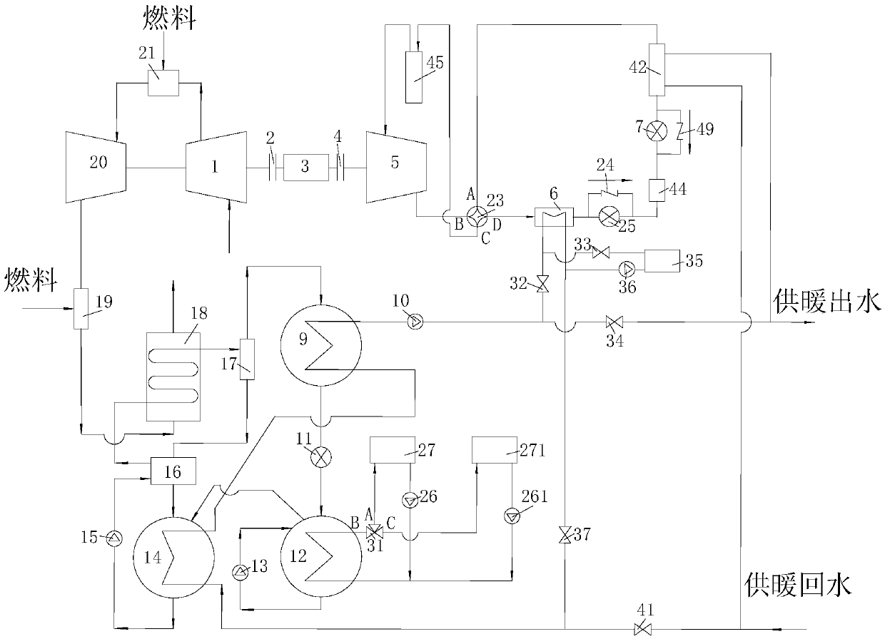
[0080] Embodiment 2. The compression-absorption composite heat pump system driven by the fuel engine of the present invention adopts the scheme 2 of a gas turbine, such as figure 2 Shown; including compressor 1, clutch 2, clutch 4, coupling 3, compressor 5, condenser 6, condenser 9, evaporator 12, absorber 14, solution heat exchanger 16, gas-liquid separator 17 , generator 18, afterburning combustion chamber 19, turbine 20, combustion chamber 21, gas-liquid separator 22, four-way valve 23 and three-way valve 31.

[0081] The outlet of compressor 1 is connected to the inlet of combustion chamber 21, the outlet of combustion chamber 21 is connected to the inlet of turbine 20, the outlet of turbine 20 is connected to the inlet of supplementary combustion chamber 19, and the turbine 20 is connected to compressor 1 and compressor 5. The outlet of the supplementary combustion chamber 19 is connected to the shell-side inlet of the generator 18, the tube bundle outlet of the generato...

Embodiment 3

[0105] Embodiment 3. The compression-steam injection compound heat pump system driven by the fuel engine of the present invention adopts the scheme 3 of the gas turbine, such as Figure 4 As shown, it includes compressor 1, clutch 2, clutch 4, coupling 3, compressor 5, condenser 6, condenser 52, evaporator 28, evaporator 50, evaporator 54, generator 18, supplementary combustion Chamber 19, turbine 20, combustion chamber 21, gas-liquid separator 22, four-way valve 23 and three-way valve 31, nozzle 58, suction chamber 57, mixing chamber 56, diffuser pipe 51.

[0106] The outlet of compressor 1 is connected to the inlet of combustion chamber 21, the outlet of combustion chamber 21 is connected to the inlet of turbine 20, the outlet of turbine 20 is connected to the inlet of supplementary combustion chamber 19, and the turbine 20 is connected to compressor 1 and compressor 5. The outlet of the supplementary combustion combustion chamber 19 is connected to the inlet of the shell si...


PUM


Abstract

The invention provides a fuel-engine-driven compression-absorption combined type heat pump system. The fuel-engine-driven compression-absorption combined type heat pump system comprises a gas compressor, a compressor, a condenser, a condenser, an evaporator, an absorber, a solution heat exchanger, a gas-liquid separator, a generator, a fuel replenishing combustion chamber, a turbine, a combustionchamber, a gas-liquid separator, a four-way valve and a three-way valve. The invention further provides an application method of the fuel-engine-driven compression-absorption combined type heat pump system. The application method comprises the steps that firstly, fuel works in an engine, output shaft work is used for driving the compressor, and steam compression heat pump cycles are implemented through the compressor; heat with the amount being several times that of the shaft work is absorbed out of a low-temperature environment, and the heat and input shaft work release heat into a middle-temperature heat source; and meanwhile, waste heat generated after the fuel works in the engine is utilized, an absorption type heat pump device is driven, the waste heat is input into an absorption typeheat pump, heat absorbed by the middle-temperature heat source, together with the input waste heat, releases heat to a high-temperature heat source through the absorption type heat pump, and therefore, the heat release amount is greater than the heat absorption amount obtained out of the middle-temperature heat source.

Description

technical field [0001] The invention relates to the technical fields of fuel, thermal energy, power, heat pump and heat supply, in particular to a compression-absorption composite heat pump heat pump system driven by a fuel engine. Background technique [0002] Heat pumps have been widely used in house heating, material heating, etc., and are highly efficient and energy-saving equipment. The performance of the heat pump is related to the temperature of the high and low temperature heat source when it is working. When the temperature difference between the high and low temperature heat source exceeds the rated working condition, the performance of the heat pump will seriously decline, or even fail to operate normally. For example, in the widely used air source heat pump heating system based on vapor compression, when the temperature drops sharply in winter, the heating capacity of the heat pump will also drop significantly, and the power consumption will increase. In severe c...

Claims


Application Information

Patent Timeline
Patent Type & Authority Applications(China)
IPC IPC(8): F25B25/02
CPCF25B25/02
Inventor 张光玉陈旭舒志成姚颖
Owner ZHEJIANG SCI-TECH UNIV
Why Eureka
Try Eureka