Automatic taking and placing device of flip polishing machine

An automatic pick-and-place, polishing machine technology, applied in grinding/polishing safety devices, grinding drive devices, grinding/polishing equipment, etc., can solve the problems of deflection of the workpiece angle, low production efficiency, and large labor input, etc. Achieve the effect of fast angle deviation correction, improve work efficiency, and reduce labor costs

Pending Publication Date: 2019-04-30
宇晶机器(长沙)有限公司
View PDF11 Cites 6 Cited by
  • Summary
  • Abstract
  • Description
  • Claims
  • Application Information

AI Technical Summary

Problems solved by technology

[0002] The products of various glass surfaces in the 3C industry are widely used, and the demand for flat and curved glass is increasing. The grinding and polishing process in the processing of curved glass requires a large amount of grinding and polishing equipment. At present, the grinding work in enterprises is done manually. When unloading, workers remove the processed glass and install unprocessed glass. During this process, the workers’ hands need to be in contact with the grinding fluid. This process requires a lot of manpower, and the working environment is harsh. The mobility of workers is high, and the overall labor cost stay high
[0004] 1. Since the grinding and polishing of curved glass uses a profiling carrier plate for positioning, the positioning accuracy of the pick-and-place material is required to be within ±0.1mm, and the existing pick-and-place device is difficult to meet the required accuracy;
[0005] 2. The angle of the workpiece after polishing will be deflected. When the manipulator grabs the workpiece and puts it into the rack, the action of correcting the angle deviation is complicated;
[0006] 3. The manipulator of the loading and unloading device picks and unloads materials with a single head, and only corresponds to a single rack, so the production efficiency is low;
[0007] 4. The design did not consider the need to moisturize the glass during production, resulting in dry products, easy to cause scratches and difficult to clean in the subsequent cleaning process

Method used


Image

  • Automatic taking and placing device of flip polishing machine
  • Automatic taking and placing device of flip polishing machine
  • Automatic taking and placing device of flip polishing machine

Examples


Embodiment Construction

[0037] In order to make the purpose, technical solution and advantages of the present invention clearer, the technical solution of the present invention will be clearly and completely described below in conjunction with specific embodiments of the present invention and corresponding drawings. Apparently, the described embodiments are only some of the embodiments of the present invention, but not all of them. Based on the embodiments of the present invention, all other embodiments obtained by persons of ordinary skill in the art without making creative efforts fall within the protection scope of the present invention.

[0038] The technical solutions provided by the embodiments of the present invention will be described in detail below in conjunction with the accompanying drawings.

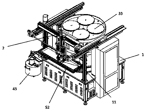
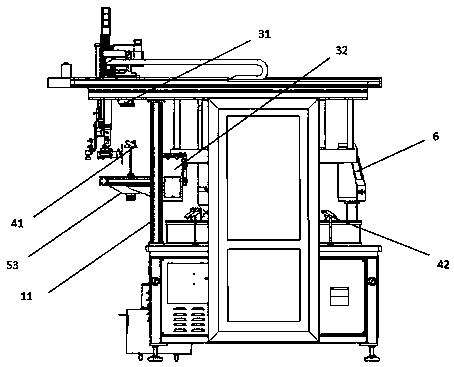
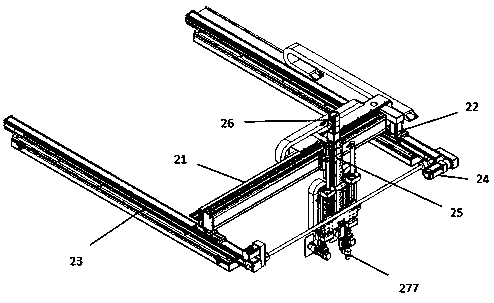
[0039] see Figure 1-8, the present embodiment comprises a frame 1, and the frame 1 is provided with a pick-and-place mechanism 2, a visual positioning mechanism 3, a spray mechanism 4, a frame-in...


PUM


Abstract

The invention discloses an automatic taking and placing device of a flip polishing machine. The automatic taking and placing device of the flip polishing machine includes a machine rack, the machine rack is provided with a taking and placing mechanism, a vision location mechanism, a mist spraying mechanism, an inserted frame mechanism and a control system, and the control system is electrically connected with the taking and placing mechanism and the visual location mechanism; the visual location mechanism includes an upper visual mechanism, a lower visual mechanism and MARK points, the upper visual mechanism is arranged on a taking and placing assembly, the lower visual mechanism is arranged at the right end of the inserted frame mechanism, and the MARK points are arranged on a tool carrying plate of a flip polishing machine body. According to the automatic taking and placing device, automatic taking and placing of a workpiece can be achieved, and the labor cost is reduced; taking andplacing are precise, the speed of angle correction of taking and placing is fast, the damaging and the scratching probabilities of the workpiece are reduced, and thus the production efficiency is improved.

Description

technical field [0001] The invention relates to the field of loading and unloading equipment for curved glass, lenses, and wafer grinding and polishing machines, in particular to an automatic loading and unloading device for a flipping polishing machine. Background technique [0002] The products of various glass surfaces in the 3C industry are widely used, and the demand for flat and curved glass is increasing. The grinding and polishing process in the processing of curved glass requires a large amount of grinding and polishing equipment. At present, the grinding work in enterprises is done manually. When unloading, workers remove the processed glass and install unprocessed glass. During this process, the workers’ hands need to be in contact with the grinding fluid. This process requires a lot of manpower, and the working environment is harsh. The mobility of workers is high, and the overall labor cost stay high. [0003] At present, the existing grinding and polishing pic...

Claims


Application Information

Patent Timeline
Patent Type & Authority Applications(China)
IPC IPC(8): B24B41/00B24B41/06B24B55/02B24B27/00B24B41/02B24B47/06
CPCB24B27/0023B24B27/0069B24B41/005B24B41/02B24B41/068B24B47/06B24B55/02
Inventor 杨佳葳王珲荣侯贤
Owner 宇晶机器(长沙)有限公司
Why Eureka
Try Eureka