Device and method for rapid detection of radon self-decay based on suppression of radon progeny

A detection device and technology of radon progeny, applied in the field of nuclear radiation detection, can solve the problems of long measurement time, long half-life of radon progeny, etc.

Active Publication Date: 2020-06-02
HENGYANG NORMAL UNIV
View PDF11 Cites 0 Cited by
  • Summary
  • Abstract
  • Description
  • Claims
  • Application Information

AI Technical Summary

Problems solved by technology

[0004] Most of the current radon detectors are based on the radiation produced by the decay of radon progeny. The half-life of radon progeny is long, and the measurement time is relatively long
In addition, the existing radon measuring device can not simultaneously obtain 222 Rn and 220 Rn concentration

Method used


Image

  • Device and method for rapid detection of radon self-decay based on suppression of radon progeny
  • Device and method for rapid detection of radon self-decay based on suppression of radon progeny
  • Device and method for rapid detection of radon self-decay based on suppression of radon progeny

Examples


Embodiment 1

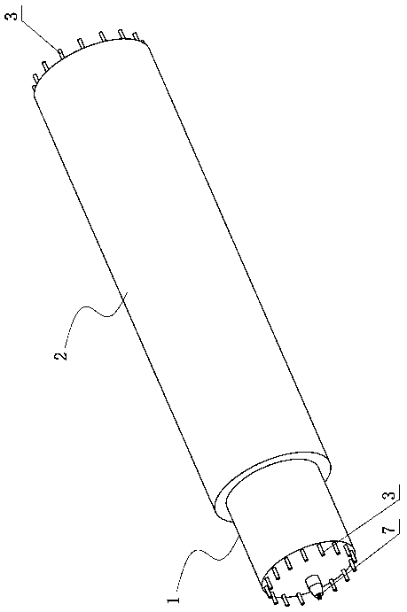
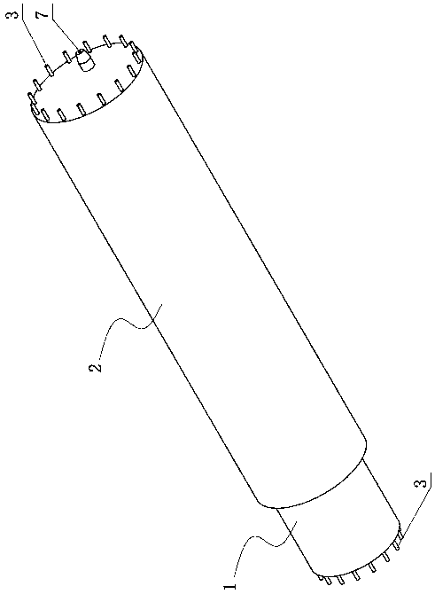
[0049] like Figure 1-7 and Figure 10 As shown, a rapid detection device for radon self-decay based on suppressing radon progeny, including a first scintillation chamber 1, a second scintillation chamber 2, a wavelength shifting optical fiber 3, a static electrode 4, an electronic readout system, and a photomultiplier tube or Silicon photomultiplier (the electronic readout system, photomultiplier tube and silicon photomultiplier are prior art, and their structures are not shown in the drawings).

[0050] The second scintillation chamber 2 is superimposed on the first scintillation chamber 1 and is connected to the first scintillation chamber 1. Both the first scintillation chamber 1 and the second scintillation chamber 2 include a plurality of cylindrical and light-tight housings 1a, 2a , the inner diameter of the housing 1a of the first scintillation chamber is smaller than the inner diameter of the housing 2a of the second scintillation chamber, all the housings 1a, 2a are...

Embodiment 2

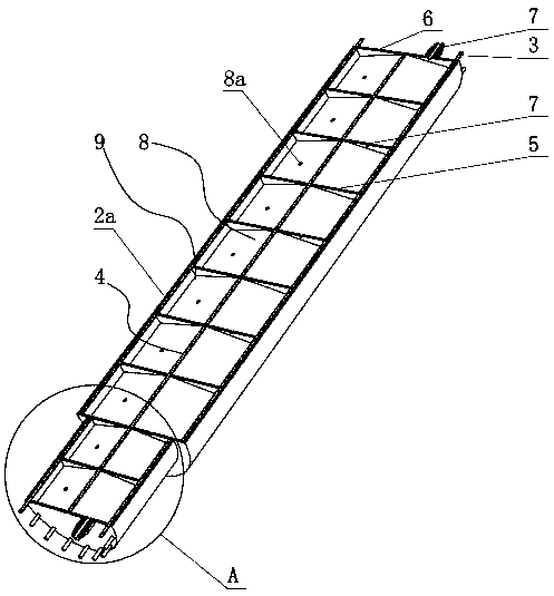
[0073] See Figure 8 and 9 As shown, the difference between this embodiment and Embodiment 1 is mainly that there are multiple static electrodes 4, and at least one static electrode 4 vertically passes through each fan-shaped chamber 9, and the static electrode 4 is close to the housing 1a , the center of the lumen of 2a is set. In addition, the above-mentioned static electrodes 4 all pass through the end caps 5 of all casings 1a, 2a above it vertically upward from the bottom layer and extend to the fan-shaped chamber 9 on the top layer. The structure of other parts of this embodiment is basically the same as that of Embodiment 1, and is detected by the device involved in this embodiment. 222 Rn and 220 The method of Rn concentration is also identical with embodiment 1, does not repeat them here.


PUM


Abstract

The invention relates to a fast detection device and method for the radon decay based on radon daughter suppression, and relates to the technical field of nuclear radiation detection. The fast detection device for radon decay based on radon daughter suppression comprises a first scintillation chamber and a second scintillation chamber, wherein both the first scintillation chamber and the second scintillation chamber include a plurality of cylindrical and light-proof shells, the inner diameter of the shells of the first scintillation chamber is less than the inner diameter of the shells of thesecond scintillation chamber, the shells are laminated from the bottom up and sequentially connected, the inner cavity of each shell is internally provided with a plurality of partition plates, and the partition plate divides the inner cavity of the shell into a plurality of fan-shaped chambers. The invention mainly improves the existing radon measurement method on the principle and methodology for radon detection. According to the invention, a fast radon detection model is constructed based on the detection radon decay, the influence of radon daughters on the detection radon is suppressed toa great extent by using electrostatic collection, filter membrane filtering and the scintillation chambers of the specific structure, and <222>Rn and <220>Rn are effectively distinguished in one measurement through the scintillation chambers of different geometric sizes.

Description

technical field [0001] The invention relates to the technical field of nuclear radiation detection, in particular to a rapid detection device and method for radon self-decay based on suppressing radon progeny. Background technique [0002] Any research and application of radon needs to measure radon, and the key core issue of radon measurement is to improve the response time and accuracy of radon measurement. The development of science and technology has produced many new methods and instruments for measuring radon concentration, such as ionization chamber method, scintillation chamber method, electrostatic collection alpha energy spectroscopy method, double filter membrane method, balloon method, activated carbon adsorption gamma energy spectroscopy method, etc. The various measurement methods mentioned above have their advantages and disadvantages. Scintillation chamber detection has been widely used in radon measurement because of its advantage of not being affected by h...

Claims


Application Information

Patent Timeline
Patent Type & Authority Patents(China)
IPC IPC(8): G01T1/167G01T1/20
CPCG01T1/167G01T1/2006
Inventor 李志强
Owner HENGYANG NORMAL UNIV
Why Eureka
Try Eureka