
Bias voltage adjustment method and device

A bias voltage adjustment and bias voltage technology, which is applied in the direction of adjusting electrical variables, control/regulation systems, instruments, etc., can solve problems such as the inability to adjust the bias voltage of a single photoelectric sensor, and achieve the effect of improving performance and high photoelectric gain

Active Publication Date: 2020-08-28
SUTENG INNOVATION TECH CO LTD
View PDF5 Cites 0 Cited by
  • Summary
  • Abstract
  • Description
  • Claims
  • Application Information

AI Technical Summary

Problems solved by technology

[0004] However, the above compensation methods cannot adjust the bias voltage of individual photosensors to the optimal bias voltage set point, and cannot achieve the best performance of photosensors

Method used


Image

  • Bias voltage adjustment method and device
  • Bias voltage adjustment method and device
  • Bias voltage adjustment method and device

Examples


Embodiment Construction

[0052] In order to make the purpose, technical solution and advantages of the present application clearer, the present application will be further described in detail below in conjunction with the accompanying drawings and embodiments. It should be understood that the specific embodiments described here are only used to explain the present application, and are not intended to limit the present application.

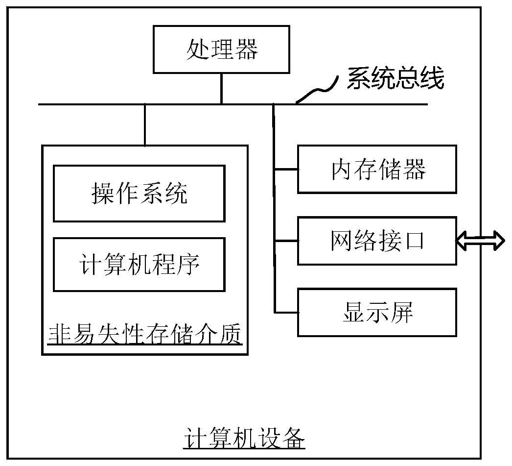
[0053] In one embodiment, a computer device is provided, the computer device may be a terminal, and its internal structure diagram may be as follows figure 1 shown. The computer device includes a processor, a memory, a network interface and a display screen connected by a system bus. Wherein, the processor of the computer device is used to provide calculation and control capabilities. The memory of the computer device includes a non-volatile storage medium and an internal memory. The non-volatile storage medium stores an operating system and computer programs. The inte...


PUM


Abstract

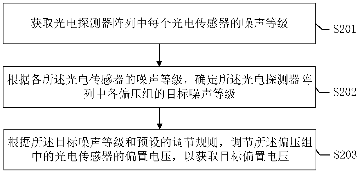
The invention relates to an offset voltage adjusting method and device. A noise level of each photosensor in a photodetector array is obtained; a target noise level of each offset voltage group in thephotodetector array is determined according to the noise level of each of the photosensors; according to the target noise level and preset adjustment rules, the offset voltage of photosensors in theoffset voltage group is adjusted to obtain the target offset voltage. The method is advantaged in that the noise is detected through a noise detector in real time, the noise range of the photosensorscan be obtained in real time, the offset voltage can be adjusted in real time by computer equipment according to the obtained noise range, the noise of the photodetector array is made to be in the reasonable range while relatively high photoelectric gain is realized, and performance of the photodetector array is improved.

Description

technical field [0001] The invention relates to the field of laser radar, in particular to a bias voltage adjustment method and device applied to laser radar. Background technique [0002] The distance measurement of lidar is extremely dependent on high-sensitivity photoelectric sensors, but due to the discreteness of the process, the bias voltage-photoelectric gain and bias voltage-noise curves of each photoelectric sensor are different; and different ambient light, temperature, device aging It will also result in a different optimal bias voltage set point. For a single photoelectric sensor, there is an optimal bias voltage so that the noise of the photodetection front end is within a reasonable range and has a high photoelectric gain. [0003] For photodetector arrays that share a single voltage in a system, there are different optimum bias voltage set points for each component. The typical practice in the industry is to keep a certain offset voltage margin and compensat...

Claims


Application Information

Patent Timeline
Patent Type & Authority Patents(China)
IPC IPC(8): G05F1/56
Inventor 邱纯鑫刘乐天
Owner SUTENG INNOVATION TECH CO LTD
Learn More