Welding wire impurity-removal mechanism for welding

A technology of welding wire and welding torch, which is applied in the field of welding wire removal mechanism, which can solve the problems of secondary pollution and single type of cleaning, and achieve the effect of preventing scratching of welding wire, improving the efficiency of removing impurities, and improving stability

Inactive Publication Date: 2019-05-07
QINGDAO YIDIAN PLASTIC WELDING EQUIP
View PDF8 Cites 2 Cited by
  • Summary
  • Abstract
  • Description
  • Claims
  • Application Information

AI Technical Summary

Problems solved by technology

The above-mentioned device is simple in structure, easy to use, easy to modify on the basis of existing equipment, and has a good cleaning effect on the surface of the welding wire. The problem is that the cleaning type is single, and the cleaning effect is affected by the cleanliness of the cleaning cotton, which is likely to cause secondary contamination , so it is necessary to invent a high-efficiency impurity removal device to solve the above problems

Method used


Image

  • Welding wire impurity-removal mechanism for welding
  • Welding wire impurity-removal mechanism for welding
  • Welding wire impurity-removal mechanism for welding

Examples


Embodiment 1

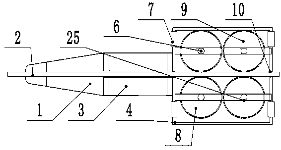
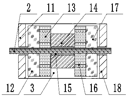
[0020] see figure 1 , a welding wire impurity removal mechanism for welding, comprising: a welding torch tip 1, a welding wire 2, a welding torch impurity removal cabin 3 and a welding wire shaping and impurity removal part 4, the welding wire 2 is a filler metal material of a molten part for welding, and the welding wire The outside of 2 is respectively equipped with welding wire shaping and removing impurities part 4, welding torch removing impurities chamber 3 and welding torch head 1 from right to left. The welding torch head 1 is fixedly installed on the outside of the welding wire 2, and the welding torch head 1 adopts a tapered structure , can effectively improve the stability of the structure of the welding torch head 1, and the front end of the conical structure can better penetrate into a narrow area for welding work and expand the scope of use. Such as figure 2 As shown, the two sides of the inside of the welding torch removal chamber 3 are respectively equipped w...

Embodiment 2

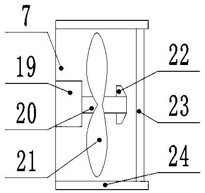
[0023] Compared with Embodiment 1, Embodiment 2 differs only in that the fan blades 21 adopt a symmetrical distribution of eight fan blades and are made of magnesium-aluminum alloy, which has good corrosion resistance and improves the stability of the equipment.

[0024] Technical principle: The welding wire 2 is shaped and removed through the welding wire shaping and removing part 4 and the welding torch removing cabin 3, which not only improves the efficiency of removing impurities but also increases the design of the shaping structure, and improves the subsequent welding quality and accuracy.


PUM


Abstract

The invention relates to the field of welding, in particular to a welding wire impurity-removal mechanism for welding. The welding wire impurity-removal mechanism for welding comprises a welding gun gun-head, a welding wire, a welding gun impurity-removal cabin and a welding wire reshaping impurity-removal part, wherein an impurity-removal cabin front supporting rod and an impurity-removal cabin rear supporting rod are separately arranged at the two sides inside the welding gun impurity-removal cabin; the inner structure of the welding wire reshaping impurity-removal part is symmetrical vertically; charge holes are formed in the middle parts of two ends of the welding wire reshaping impurity-removal part; a rotary rod is fixedly mounted above the welding wire reshaping impurity-removal part; and a fan part is arranged at the upper end of the welding wire reshaping impurity-removal part. Threads at the tail end of the rotary shaft are fixedly equipped with limiting screws which can limit fan blades, so that dropping during high-speed rotation is prevented; and a filter screen which is a nylon wire screen is arranged at the right end of the fan bracket, so that dust in air can be effectively prevented from entering; and impurities on the surface of the front roller and the surface of the rear roller can be discharged through suction force of a fan.

Description

technical field [0001] The invention relates to the field of welding, in particular to a welding wire impurity removal mechanism for welding. Background technique [0002] Welding, also known as welding or welding, is a manufacturing process and technology that uses heat, high temperature or high pressure to join metal or other thermoplastic materials such as plastics. During the welding process, if the atmosphere is in direct contact with the high-temperature molten pool, the oxygen in the atmosphere will oxidize the metal and various alloying elements. Nitrogen and water vapor in the atmosphere enter the molten pool, and defects such as pores, slag inclusions, and cracks will be formed in the weld during the subsequent cooling process, deteriorating the quality and performance of the weld. In order to improve the welding quality, various protection methods have been developed. For example, gas shielded arc welding uses argon, carbon dioxide and other gases to isolate the...

Claims


Application Information

Patent Timeline
Patent Type & Authority Applications(China)
IPC IPC(8): B23K3/06B23K3/08
Inventor 赵恩喜
Owner QINGDAO YIDIAN PLASTIC WELDING EQUIP
Why Eureka
Try Eureka