Detection system for spectral resolution of Rowland grating spectrometer
A technology of spectral resolution and Roland grating, applied in the field of detection system of spectral resolution of Roland grating spectrometer, can solve the problems of Roland grating curvature radius deviation, the actual spectral resolution cannot reach the design index, the slit width does not match the design value, etc. , to achieve the effect of good stability, low operating cost and high flexibility
- Summary
- Abstract
- Description
- Claims
- Application Information
AI Technical Summary
Problems solved by technology
Method used
Image

Examples
Embodiment
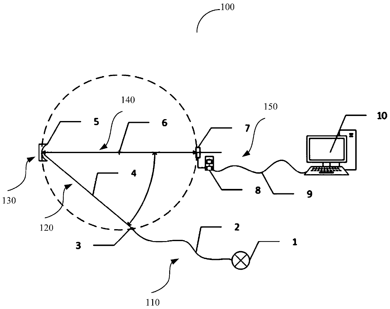
[0046] Taking the Roland grating spectrometer to be tested as an example with a radius of curvature R750mm; grating aperture Φ63.5mm; spectral order -1; groove density 2400g / mm; incident angle 40°; figure 1 This embodiment will be described.
[0047] First use the laser to adjust the state of the grating to the test state, that is, the spectra of each order are on the same horizontal plane, and the image of the outgoing spectrum is parallel to the direction of the grating lines, and the Roland system to be tested is adjusted according to the design parameters by adjusting the incident cantilever. The front and rear positions and incident angles of the slits are connected to a line-spectrum light source such as a mercury lamp. According to the parameters such as the incident angle of the Roland grating, the length of the incident arm, the grating line, and the radius of curvature, the line-spectrum light source connected through the grating equation is relatively similar. The e...
PUM
 Abstract
Description
Claims
Application Information
PatSnap Eureka turns technology decisions into work you can execute. Powered by our Innovation Knowledge Graph, it runs expert workflows across engineering, life sciences, materials and intellectual property. Get your review-ready output in minutes.


