Dynamic super-resolution fluorescence imaging technology

A super-resolution imaging and super-resolution imaging technology, applied in the field of super-resolution fluorescence imaging, can solve the problems of aggravating the fluorescence bleaching and phototoxicity of the sample, and taking a long time.

Pending Publication Date: 2019-05-07
黄晓淳
View PDF0 Cites 3 Cited by
  • Summary
  • Abstract
  • Description
  • Claims
  • Application Information

AI Technical Summary

Problems solved by technology

[0003] STED, SSIM/NSIM and other methods require higher intensity laser illumination than traditional fluorescence imaging methods, which seriously aggravate the fluorescence bleaching and phototoxicity of the sample compared with the weak light illumination of traditional fluorescence imaging; RESOLFT/PALM/FPALM/STORM Methods such as PALM/FPALM/STORM and other molecular positioning methods need to repeatedly turn on/off fluorescent molecules, and the fluorescent molecules will be bleached after multipl...

Method used


Image

  • Dynamic super-resolution fluorescence imaging technology
  • Dynamic super-resolution fluorescence imaging technology
  • Dynamic super-resolution fluorescence imaging technology

Examples


Embodiment 1

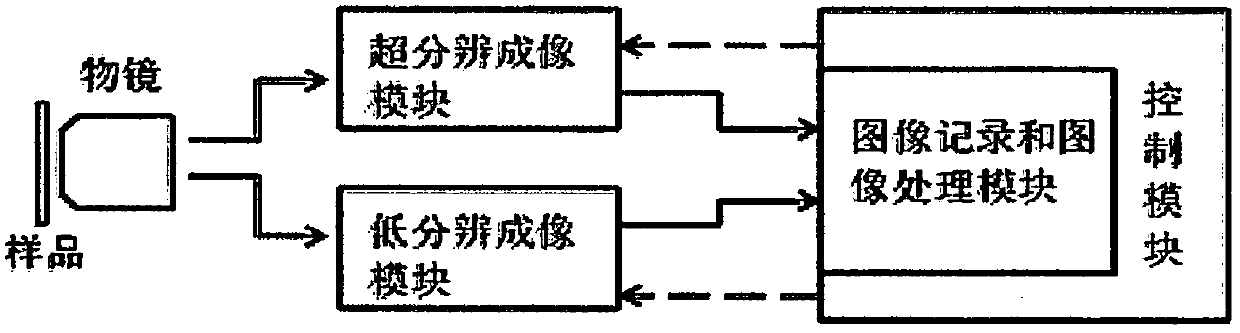
[0094] The general structure of the optical path of embodiment one is as follows Figure 6 As shown, in this embodiment, STED is used for super-resolution imaging, and common scanning confocal method is used for low-resolution imaging. The super-resolution imaging module and the low-resolution imaging module share multiple components in the optical path, including: objective lens, lens group, spot scanning module, mirror, dichromatic mirror 1 / 2, band-pass filter, optical fiber, detector, The excitation light; the loss light belongs to the super-resolution imaging module. Although the super-resolution imaging module and the low-resolution imaging module share most of the optical path components, functionally speaking, the control module can turn off or turn on the lost light to switch between super-resolution imaging and low-resolution imaging, so it meets the figure 1 The structural block diagram shown; and, because the imaging optical path is shared, the field of view of the...

Embodiment 2

[0095] The general structure of the light path of embodiment two is as Figure 7 As shown, in this embodiment, STED is used for super-resolution imaging and total internal reflection illumination is used for low-resolution imaging. The components included in the super-resolution imaging module are: lens group, spot scanning module, mirror, dichromatic mirror 1 / 2, band-pass filter, optical fiber, detector, phase plate, excitation light, lost light; low-resolution imaging module The components included are: prism, bandpass filter, CCD camera, and TIRF excitation light; the components shared by the two modules are: objective lens and beam splitter. The super-resolution imaging module and the low-resolution imaging module are separated by a beam splitter. The control module controls the opening and closing of excitation light, depletion light, and TIRF excitation light, and can switch between super-resolution imaging and low-resolution imaging. In low-resolution imaging, the TIR...


PUM


Abstract

The invention provides a dynamic super-resolution fluorescence imaging technology. The invention relates to the super-resolution fluorescence imaging technology capable of capturing dynamic images. (1) A fluorescence microscopic imaging device is capable of super-resolution imaging and low-resolution imaging, and the field of view regions and object planes observed by two imaging modes are the same. For the same observation object, an image acquired by convolution of a super-resolution image and a conversion function is equivalent to a low-resolution image, and the conversion function is measured. (2) A dynamic image capturing and image processing method corresponding to the device comprises the steps that super-resolution and low-resolution modules are alternately used for continuous capturing through sequential control, and images are recorded and saved as a video; image processing is carried out; a small proportion of super-resolution images in the original video are taken as priorknowledge; the measured conversion function is combined; and low-resolution images in the original video are converted into super-resolution images through speculative calculation. The dynamic super-resolution fluorescence imaging technology provided by the invention is used for acquiring dynamic super-resolution images with high time resolution and long time.

Description

technical field [0001] The invention relates to the technical field of super-resolution fluorescence imaging, in particular to a super-resolution fluorescence imaging method capable of shooting dynamic images and capable of time resolution. Background technique [0002] Fluorescence microscopy is very suitable for imaging biomolecules, cells, etc. due to its far-field, non-invasive characteristics. Traditional fluorescence microscopes (such as wide-field illumination, scanning confocal, total internal reflection illumination, etc.) are limited by the Abbe diffraction limit, and their spatial resolution cannot be better than 200nm, so they cannot distinguish finer structures. In the past ten years, a variety of fluorescence imaging methods that break through the diffraction limit have been developed, called super-resolution imaging, such as stimulated emission depletion imaging (STED), reversible saturation / switching optical transition imaging (RESOLFT), and photoactivated lo...

Claims


Application Information

Patent Timeline
IPC IPC(8): G01N21/64
Inventor 黄晓淳
Owner 黄晓淳
Why Eureka
Try Eureka