A method for suppressing DC oscillation over-current impact when the subway energy-feedback device exits

An energy-feedback technology at the time of exit, applied in the field of power electronics, can solve the problems of increasing device volume, increasing loss, and increasing device hardware cost by LC branch, achieving high engineering value, ensuring reliability and safety, and ensuring reliability.

Active Publication Date: 2022-03-25
NANJING APAITEK TECH
View PDF7 Cites 0 Cited by
  • Summary
  • Abstract
  • Description
  • Claims
  • Application Information

AI Technical Summary

Problems solved by technology

[0004] The existing public technologies include: Patent No. CN108631603A, a control method based on full-bridge converter DC bus voltage oscillation suppression. It is proposed that the oscillation on the DC side can be controlled by adding an LC branch to control its volt-ampere characteristic into a resistance characteristic. The method can suppress the DC Oscillation, although this method can suppress DC oscillation, and can avoid the problem of increasing loss caused by directly increasing the resistance, but increasing the LC branch needs to increase the hardware cost of the device, and also need to increase the volume of the device; Patent No. CN104638634A master-slave mode The DC microgrid oscillation suppression method based on the band-pass filter can solve the problem of DC side oscillation when the converter circuit is working, but it cannot suppress the oscillation under the condition that the energy feeder device pulse blockade exits. and the role of protective devices

Method used


Image

  • A method for suppressing DC oscillation over-current impact when the subway energy-feedback device exits
  • A method for suppressing DC oscillation over-current impact when the subway energy-feedback device exits

Examples


Embodiment Construction

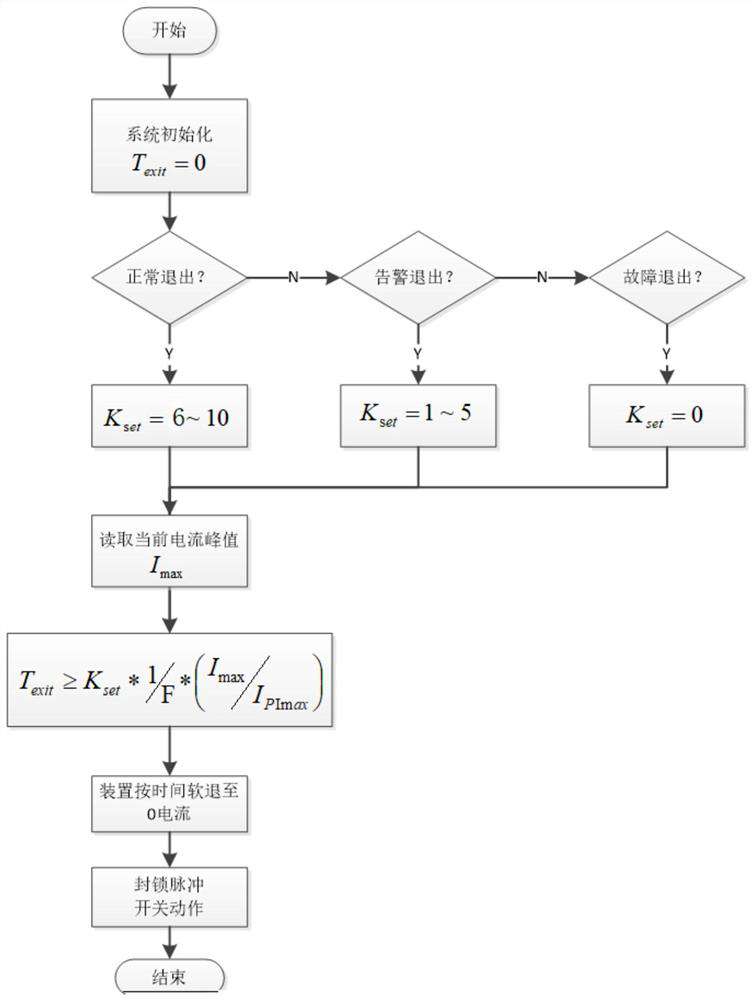
[0023] When the subway energy feeder is withdrawn, before blocking the PWM pulse, it is necessary to increase the time adjustment coefficient T in order to suppress the impact of the DC oscillating current spike. exit , reducing the current rate of change.

[0024] attached figure 1 This is the system closed-loop control block diagram with the time adjustment coefficient added in the present invention. According to the voltage outer loop PI controller, the active tracking current command Id* is obtained. When the device exits, the command current is adjusted by the time adjustment coefficient T. exit Obtain the current command at the time of exit, inversely transform the current to obtain the AC output command, and make a difference with the actual current, and then pass through the PI+PR controller to obtain the three-phase output current modulation amount, and finally output the PWM drive IGBT through the pulse modulation module. switch action. When the device is ready to...


PUM


Abstract

The invention relates to a method for suppressing DC oscillation overcurrent impact when a subway energy feeder device exits, comprising the following steps: first reading the working current of the subway energy feeder device and the initial value of the maximum current change; the initial value of the maximum current change is outside the DC voltage Loop PI controller output value. 2. According to the type of working conditions when the subway energy feedback device exits, different ranges of adjustment coefficients are preset. 3. Calculate the time required for the exit of the subway energy feedback device; 4. Invert the current command at the time of exit and make a difference with the actual current, then input it to the PI+PR controller to obtain the three-phase output current modulation. 5. Control the current of the subway energy feeder device to be 0 after time passes. The three-phase output current modulation value is input to the PWM driver through the pulse modulation module, and the PWM driver controls the IGBT to make corresponding switching actions. Six devices exit. This method can greatly suppress the current peak caused by the DC oscillation when the subway energy feed device exits.

Description

technical field [0001] The invention belongs to the technical field of power electronics, and in particular relates to a method for suppressing DC oscillation overcurrent shock when a subway energy feeder is withdrawn. Background technique [0002] The subway energy feeder is a device that absorbs energy and feeds it back to the power grid due to frequent subway braking. It consists of a controller, a collection device, an IGBT, a filter, a DC capacitor, and a protection switch. In addition to the AC side of the converter, the subway energy feeder has LCL or other types of filters to filter out the sub-harmonics of the switching frequency to prevent pollution of the power grid. On the DC side, because it is connected to the traction network, in order to filter out the DC ripple, all the subway The energy-feeding device needs to add a DC reactance on the DC side for filtering, and the DC reactance can also play a role in suppressing the short-circuit current on the DC side. ...

Claims


Application Information

Patent Timeline
Patent Type & Authority Patents(China)
IPC IPC(8): H02J1/14
Inventor 陈蕾仇志凌李锦胡磊磊张明张勇刘苏成张立飞
Owner NANJING APAITEK TECH
Why Eureka
Try Eureka