An adjustable strong sound horn manufacturing fixture

An adjustable horn technology, applied in the direction of manufacturing tools, metal processing equipment, auxiliary welding equipment, etc., can solve the problems of increased scrap rate, extended production cycle, increased production cost, etc., to improve the sound quality and decibels of the horn, and improve the sound quality. Consistency, avoiding the effect of position changes

Active Publication Date: 2021-02-12
赵庆杰
View PDF11 Cites 0 Cited by
  • Summary
  • Abstract
  • Description
  • Claims
  • Application Information

AI Technical Summary

Problems solved by technology

[0003] 1. For the production of the horn part, most of the horns are made by traditional handwork. It is difficult to achieve batch processing and ensure the curve meshing of the horn. Therefore, due to factors such as production technology, it is often difficult to ensure that the sound quality of the batch horn and the decibel test of the horn sound reach The ideal design value, so it is necessary to re-make the horn in combination with the actual processing conditions, but the manufactured horn is still difficult to meet the theoretical design standard, and the production cycle is prolonged, resulting in waste of raw materials
[0004] 2. Most of the existing horn molds are only suitable for the manufacture of circular horns. When processing horns of different shapes and specifications, corresponding matching designs are required. Therefore, the applicability of horn molds is low. At the same time, for horns of different shapes The way in which the corresponding molds are designed also increases the production cost
[0005] 3. In the production process of the horn part, it is difficult to ensure the good consistency of the overall shape and position of the horn part, so it is easy to increase the scrap rate in mass production

Method used


Image

  • An adjustable strong sound horn manufacturing fixture
  • An adjustable strong sound horn manufacturing fixture
  • An adjustable strong sound horn manufacturing fixture

Examples


Embodiment Construction

[0031] In order to better understand the present invention, the present invention will be further described below in conjunction with specific embodiments and accompanying drawings.

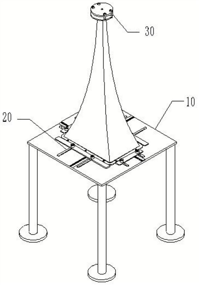
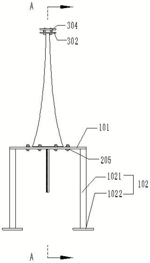
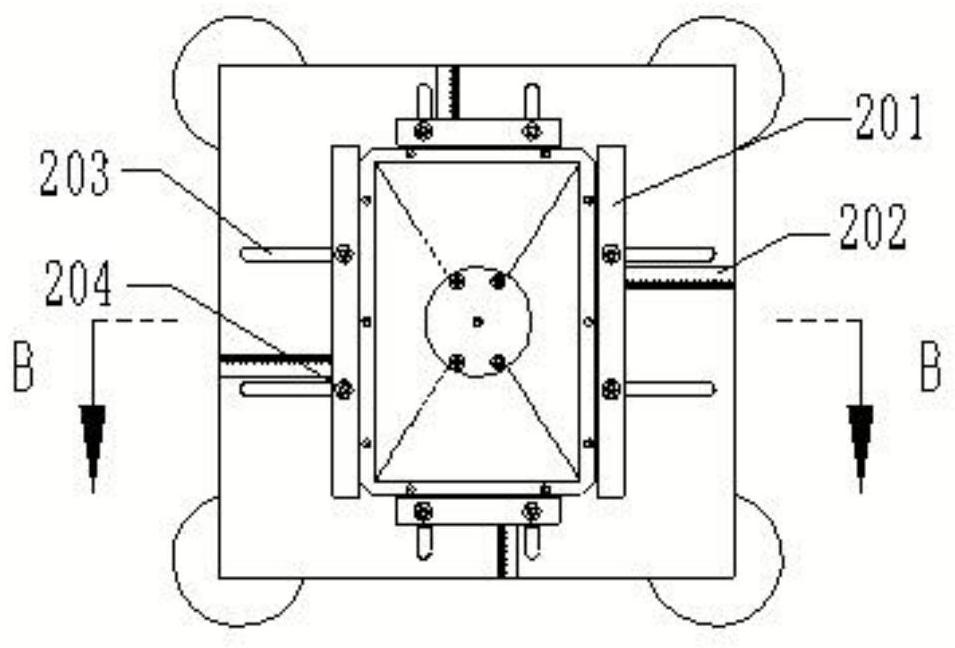
[0032] like Figure 1-Figure 6 As shown, an adjustable strong-sounding horn manufacturing jig includes a horn jig main body and a base 10. The horn jig main body is set to consist of a horn mouth adjustment mechanism 20 and a horn height adjustment mechanism 30. The horn mouth adjustment mechanism 20 is horizontally arranged on the base 10, the lower part of the horn height adjustment mechanism 30 is vertically installed in the center of the base 10, through the cooperation of the horn mouth adjustment mechanism 20 and the horn height adjustment mechanism 30, the horn mouth adjustment mechanism 20 can be placed on the base according to actual production needs. 10 to ensure the size of the mouth of the horn to be produced, and the horn height adjustment mechanism 30 can be adjusted in the height d...


PUM


Abstract

The present invention provides an adjustable strong-sounding horn manufacturing jig, including a horn jig main body and a base. The horn jig main body is set to consist of a horn mouth adjustment mechanism and a horn height adjustment mechanism. The horn mouth adjustment mechanism is horizontally arranged on the On the base, the lower part of the horn height adjustment mechanism vertically passes through the center of the base. The invention adopts the device, which is simple and practical, and can conveniently manufacture horns of different types and specifications in batches, and ensure good consistency of the overall shape of the horn and the size of each position, thereby effectively improving the sound quality and sound decibels of the finished horn, and reducing production costs And shorten the horn manufacturing process time.

Description

technical field [0001] The invention relates to the technical field of auxiliary equipment for manufacturing horns, in particular to an adjustable jig for manufacturing strong-sounding horns. Background technique [0002] The horn speaker is composed of a horn and a driver. Because of its high sound transmission efficiency and strong sound radiation direction control, the horn speaker has the function of maintaining stability and deterring, so it is used in various professional performances, public places and It is widely used in military, security, rescue and other aspects. Among them, since the horn part needs to cooperate with different drivers to meet various needs, the horn itself will also have ever-changing geometric shapes. In order to improve sound transmission efficiency, control the width of sound radiation, or reduce distortion in sound diffusion, etc., many different horns need to be designed. However, the existing manufacturing method for the horn part has th...

Claims


Application Information

Patent Timeline
Patent Type & Authority Patents(China)
IPC IPC(8): B23K37/04
Inventor 赵庆杰
Owner 赵庆杰
Why Eureka
Try Eureka