Silicon dioxide drying and impurity removing system
A technology of silicon dioxide and drying device, applied in drying, drying machine, drying of solid materials, etc., can solve the problems of affecting product quality, easy residual iron filings, etc., to improve filtration effect, filtration rate and drying efficiency High and improve work efficiency
- Summary
- Abstract
- Description
- Claims
- Application Information
AI Technical Summary
Problems solved by technology
Method used
Image
Examples
Embodiment 1
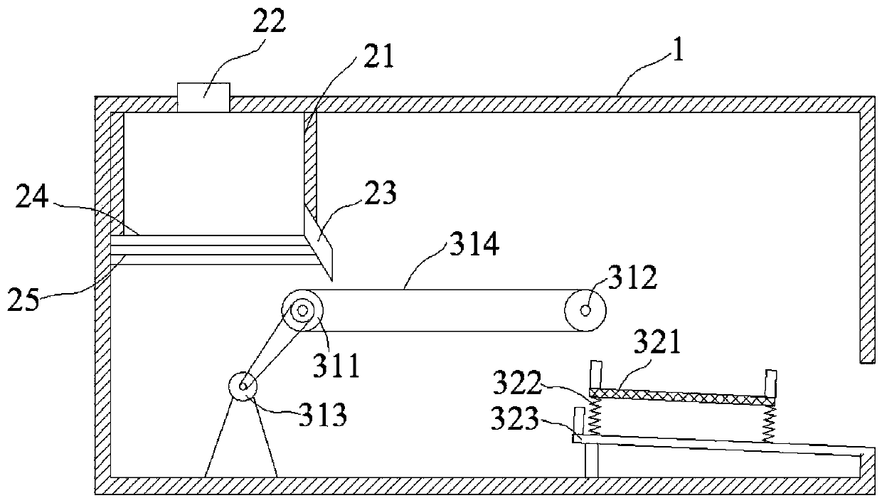
[0038] Such as figure 1 As shown, the silica drying and impurity removal system includes a frame 1, a drying device, and an impurity removal device;
[0039] The impurity removal device includes a first impurity removal device and a second impurity removal device;
[0040] The drying device is located on the frame 1, and the drying device includes a drying box 21, the top of the drying box 21 is provided with a feed port 22, and the drying box 22 is provided with a discharge port 23, and the silicon dioxide is The discharge port 23 falls on the first impurity removal device 31; the bottom of the drying box 21 is provided with an interlayer 24, and a heating device 25 is arranged in the interlayer 24, and the heating device 25 is a resistance wire in this embodiment.
[0041] The first impurity removal device 31 comprises a driving roller 311, a driven roller 312 and a motor 313, the driven roller 311 and the driving roller 312 are connected by a transmission belt 314, and the...
Embodiment 2
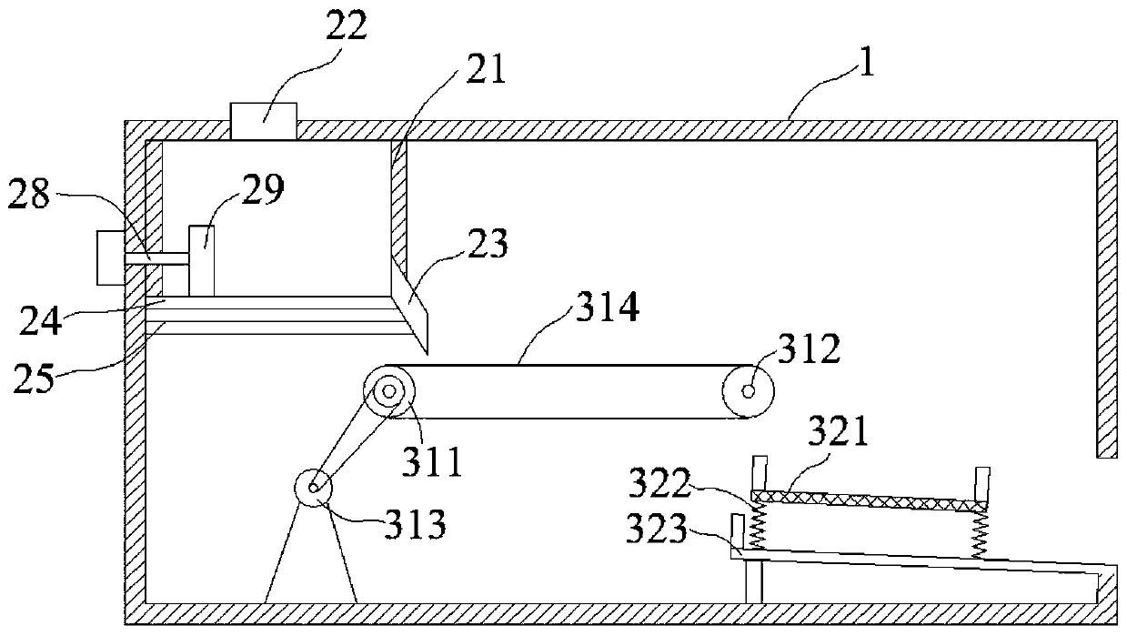
[0047] Such as figure 2 As shown, the silica drying and impurity removal system also includes a material guide trough 26, a material guide baffle 27, a telescopic device 28, and a push plate 29;
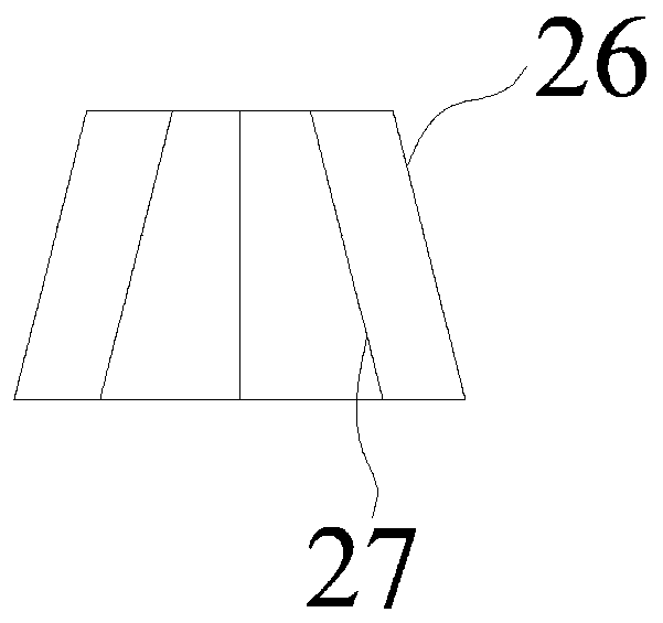
[0048] The discharge opening 23 of drying casing 21 is positioned at the side wall of drying casing 21, is provided with material guide groove 26 in the discharge opening 23, as image 3 Shown, material guide chute 26 is trumpet shape, and material guide chute 26 is provided with some material guide baffles 27, and the number of material guide baffles 27 can be set according to actual needs, and the whereabouts of material guide baffle 27 and silicon dioxide The directions are parallel, and the silicon dioxide falls on the conveyer belt 314 along the chute 26 .
[0049] The discharge port 23 is provided with a telescopic device 28 and a push plate 29 in the opposite direction. The telescopic device 28 is located on the frame 1. The telescopic device 28 is connected with the push pl...
Embodiment 3
[0053] Such as Figure 4 As shown, the silica drying and impurity removal system also includes an impurity collection tank 315, a first material guide plate 316, a second material guide plate 317, and a bracket 318;
[0054] The following of the driven roller 312 is provided with a debris collection tank 315, the debris collection groove 315 is connected with a first material guide plate 316, and the debris falls from the driven roller 312 onto the first material guide plate 316, thereby falling into the In the debris collection tank 315.
[0055] The screen frame 321 is inclined, and the bottom surface of the material collection tank 323 is inclined, and the lower side of the bottom surface of the material collection tank 323 is the discharge end; the bottom of the material collection tank 323 is provided with a support 324, and one end of the support 324 It is connected with the bottom surface of the material collection tank 323, and the other end is connected with the fram...
PUM
 Abstract
Description
Claims
Application Information
 - R&D
- Intellectual Property
- Life Sciences
- Materials
- Tech Scout
- Unparalleled Data Quality
- Higher Quality Content
- 60% Fewer Hallucinations
Browse by: Latest US Patents, China's latest patents, Technical Efficacy Thesaurus, Application Domain, Technology Topic, Popular Technical Reports.
© 2025 PatSnap. All rights reserved.Legal|Privacy policy|Modern Slavery Act Transparency Statement|Sitemap|About US| Contact US: help@patsnap.com


