
Dry quenching furnace system with tail gas desulfurizing function and desulfurizing method thereof

A dry quenching furnace and functional technology, applied in the field of CDQ furnace system, can solve the problems of high cost, unfavorable production running, and great influence on field equipment space, and achieve the effect of reducing production cost and reducing the influence of equipment space.

Pending Publication Date: 2019-05-17
NANJING IRON & STEEL CO LTD
View PDF6 Cites 0 Cited by
  • Summary
  • Abstract
  • Description
  • Claims
  • Application Information

AI Technical Summary

Problems solved by technology

[0002] The dry coke quenching process is a kind of coke quenching process for ironmaking coke. In this process, part of the circulating gas (tail gas) needs to be discharged, and some coke powder particles and contained SO 2 Impurities will be discharged along with the exhaust gas. Although most of the coke powder particles will be recovered after bag dust removal before discharge, the concentration of particulate matter in the emission index can reach the special discharge standard for air pollutants stipulated in GB16171-21012 "Emission Standards for Pollution from the Coking Chemical Industry" , but due to the effect of bag dust removal on SO removal 2 Ineffective, resulting in SO in the exhaust 2 The emission value is as high as 150mg / m 3 , seriously exceeding the standard limit of 80mg / m 3
Existing tail gas desulfurization processes are all implemented for tail gas release devices, which require additional desulfurization reactors and dust removal equipment, which are costly and have a great impact on the site equipment space, which is not conducive to smooth production

Method used


Image

  • Dry quenching furnace system with tail gas desulfurizing function and desulfurizing method thereof

Examples


Embodiment Construction

[0014] Below, the present invention will be described in further detail in conjunction with the accompanying drawings.

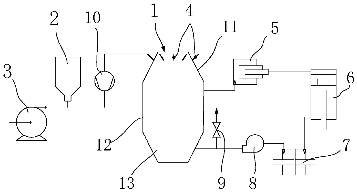
[0015] Such as figure 1 As shown, a CDQ furnace system with tail gas desulfurization function includes a furnace body 1, a desulfurizer bin 2, a pneumatic conveying device 3, a plurality of blowing pipes 4, a primary dust collector 5, a waste heat boiler 6, and a secondary dust collector 7 , Circulation fan 8, gas diffuser 9 and distributor 10.

[0016] Its working principle is: the powdery desulfurizer is transported to the top of the inner chamber of the furnace body, and the SO in the circulating gas in the furnace is mixed with the powdery desulfurizer during the falling process. 2 The reaction produces sulfate particles, some of which fall into the coke layer and are sent to the blast furnace to participate in smelting along with the coke, and the other part of the particles enters the dust collector with the circulating gas for dust removal and filtra...


PUM


Abstract

The invention discloses a dry quenching furnace system with a tail gas desulfurizing function and a desulfurizing method thereof. The dry quenching furnace system is characterized in that a spraying pipe is distributed in the circumferential direction of a top cone of a dry-quenching furnace; a powdery desulfurizing agent is sprayed into the furnace body through a pneumatic conveying device; the powdery desulfurizing agent reacts with SO2 in recycle gas inside the furnace in a falling process to generate sulfate particles; a part of the sulfate particles fall into a coke layer and is conveyedinto a blast furnace along with coke to participate in smelting, and the other part of the sulfate particles enter a deduster along with the recycle gas for dedusting and filtering; residual filteredrecycle gas is discharged by a gas exhaust device. Thus, SO2 in exhaust tail gas is effectively removed, so that the SO2 emission value can reach 80 mg / m<3> or below. In the system, a desulfurizing reactor and dedusting equipment do not need to be added, and tail gas desulfurization can be realized in the dry-quenching furnace, so that the production cost is effectively lowered, and the influenceon the space of the field equipment is lowered.

Description

technical field [0001] The invention relates to a dry quenching furnace, in particular to a dry quenching furnace system with tail gas desulfurization function and a desulfurization method of the system. Background technique [0002] The dry coke quenching process is a kind of coke quenching process for ironmaking coke. In this process, part of the circulating gas (tail gas) needs to be discharged, and some coke powder particles and contained SO 2 Impurities will be discharged along with the exhaust gas. Although most of the coke powder particles will be recovered after bag dust removal before discharge, the concentration of particulate matter in the emission index can reach the special emission standard for air pollutants stipulated in GB16171-21012 "Emission Standard of Pollution for Coking Chemical Industry" , but due to the effect of bag dust removal on SO removal 2 Ineffective, resulting in SO in the exhaust 2 The emission value is as high as 150mg / m 3 , seriously ex...

Claims


Application Information

Patent Timeline
Patent Type & Authority Applications(China)
IPC IPC(8): B01D53/50B01D46/00C10B39/02B01D53/83
Inventor 吴顺端
Owner NANJING IRON & STEEL CO LTD
Learn More