Method for treating garbage, cracking furnace and cracking device thereof

A technology for waste treatment and cracking device, which is applied in the petroleum industry, preparation of liquid hydrocarbon mixtures, etc., and can solve the problems of long time, large area, soil pollution, etc.

Inactive Publication Date: 2019-05-17
河南银洲新型建材有限公司
View PDF6 Cites 0 Cited by
  • Summary
  • Abstract
  • Description
  • Claims
  • Application Information

AI Technical Summary

Problems solved by technology

[0002] With the continuous development of urbanization, garbage, as a product of urban metabolism, used to be a burden on urban development. Many cities in the world have been surrounded by garbage. Now, with the continuous development of science and technology, garbage has become the most potential urban resource. , the commonly used urban waste treatment methods today are mainly to pretreat the waste and landfill it for fertilizer production, biogas power generation, cracking oil production, and biochemical treatment. However, landfill treatment will occupy a large area, and a large amount of orga

Method used


Image

  • Method for treating garbage, cracking furnace and cracking device thereof
  • Method for treating garbage, cracking furnace and cracking device thereof
  • Method for treating garbage, cracking furnace and cracking device thereof

Examples


Embodiment 1

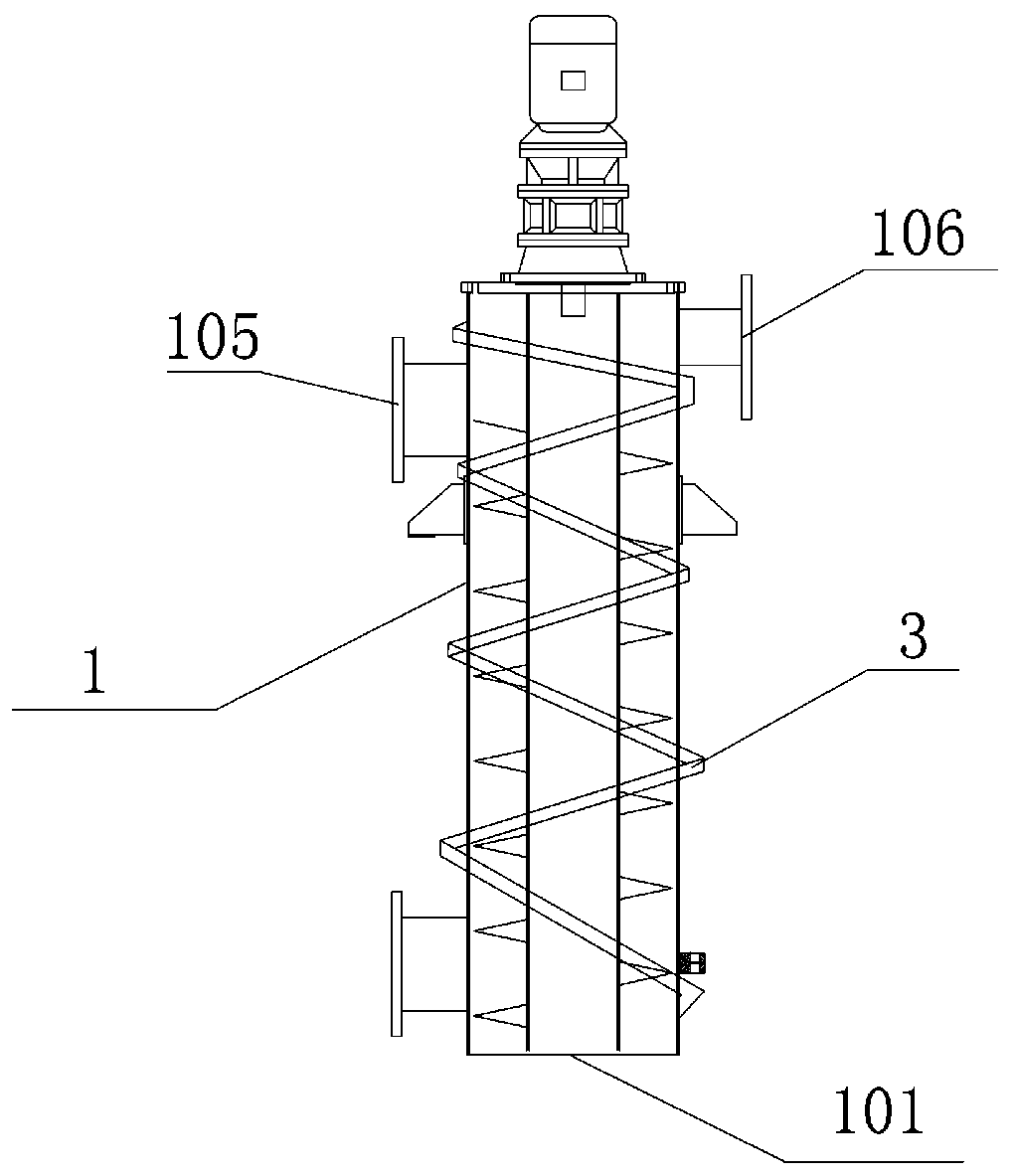
[0032] figure 1 It is a kind of cracking furnace, the inner wall of the cracking furnace is covered with SiC layer, the outer wall of the cracking furnace is wound with electromagnetic wire 3, and the electromagnetic wire 3 is connected to a power supply, and the furnace body is provided with a feed port and a discharge port. The cracking furnace is Vertical cracking furnace 1, the upper side wall of vertical cracking furnace 1 is provided with vertical cracking furnace feed port 105 and vertical cracking furnace flue gas outlet 106, and the lower part of vertical cracking furnace 1 is provided with vertical cracking furnace discharge port 101 .

Embodiment 2

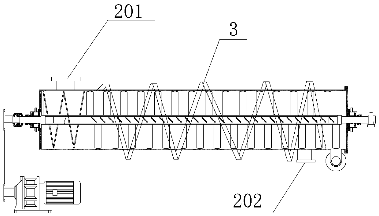
[0034] figure 2 It is a kind of cracking furnace, the inner wall of the cracking furnace is covered with SiC layer, the outer wall of the cracking furnace is wound with electromagnetic wire 3, and the electromagnetic wire 3 is connected to a power supply, and the furnace body is provided with a feed port and a discharge port. The cracking furnace is Horizontal cracking furnace 2 , the horizontal cracking furnace feed port 201 is arranged above the horizontal cracking furnace 2 , and the horizontal cracking furnace discharge port 202 is arranged below the horizontal cracking furnace 2 .

Embodiment 3

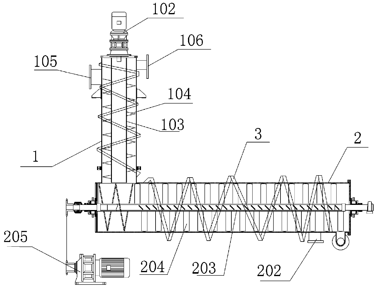
[0036] Such as Figure 3-13 Shown, a kind of cracking device, the inner wall of described cracking furnace covers SiC layer, and this cracking device comprises vertical cracking furnace 1, and the lower end of vertical cracking furnace 1 communicates with horizontal cracking furnace 2, and vertical cracking furnace 1 and The outer wall of the horizontal cracking furnace 2 is wound with a magnet wire 3, and the magnet wire 3 is connected to a power source. The inner wall of the furnace body of the vertical cracking furnace 1 and the horizontal cracking furnace 2 is covered with a SiC layer.

[0037] The upper end face of described vertical cracking furnace 1 is provided with stirring motor 102, and the output shaft of stirring motor 102 runs through vertical cracking furnace 1 and connects stirring feeding shaft 103, and the length direction of stirring feeding shaft 103 is the same as the length of vertical cracking furnace 1. Direction is the same, the outer wall of stirring ...


PUM


Abstract

The invention belongs to the technical field of garbage treatment and specifically relates to a method for treating garbage, a cracking furnace and a cracking device thereof. The method for treating garbage comprises the following steps: pretreating garbage and then mixing with calcium carbonate powder; cracking in the cracking furnace, thereby forming biomass charcoal and high-temperature smoke at 200-350 DEG C; discharging the high-temperature smoke and condensing into liquid oil. The method is high in cracking speed, environment-friendly and energy-saving.

Description

technical field [0001] The invention belongs to the technical field of garbage treatment, and in particular relates to a garbage treatment method, a cracking furnace and a cracking device. Background technique [0002] With the continuous development of urbanization, garbage, as a product of urban metabolism, used to be a burden on urban development. Many cities in the world have been surrounded by garbage. Now, with the continuous development of science and technology, garbage has become the most potential urban resource. , the commonly used urban waste treatment methods today are mainly to pretreat the waste and landfill it for fertilizer production, biogas power generation, cracking oil production, and biochemical treatment. However, landfill treatment will occupy a large area, and a large amount of organic matter and The landfill of batteries and other substances will cause a lot of pollution to the soil. Both fertilizer making and biochemical treatment require a lot of ...

Claims


Application Information

Patent Timeline
IPC IPC(8): C10G1/00
Inventor 朱新法孔龙子
Owner 河南银洲新型建材有限公司
Why Eureka
Try Eureka