
Method and device for preventing distillation scaling

A technology of distillation tower and distillation tray, which is applied in the direction of cleaning methods using tools, distillation separation, separation methods, etc., which can solve the problems affecting the stable and continuous operation of the ammonia distillation system, pollution, and increasing the operating cost of ammonia removal equipment, etc.

Pending Publication Date: 2019-05-21
JIANGSU WODEKAI ENVIRONMENTAL PROTECTION TECH CO LTD
View PDF0 Cites 2 Cited by
  • Summary
  • Abstract
  • Description
  • Claims
  • Application Information

AI Technical Summary

Problems solved by technology

[0007] At present, the conventional method is to use dilute acids such as sulfamic acid and nitric acid to clean the trays, which not only affects the stable and continuous operation of the ammonia distillation system, but also greatly increases the operating cost of the deamination equipment due to the consumption of cleaning agents, and produces new pollution.

Method used


Image

  • Method and device for preventing distillation scaling
  • Method and device for preventing distillation scaling
  • Method and device for preventing distillation scaling

Examples


Embodiment 1

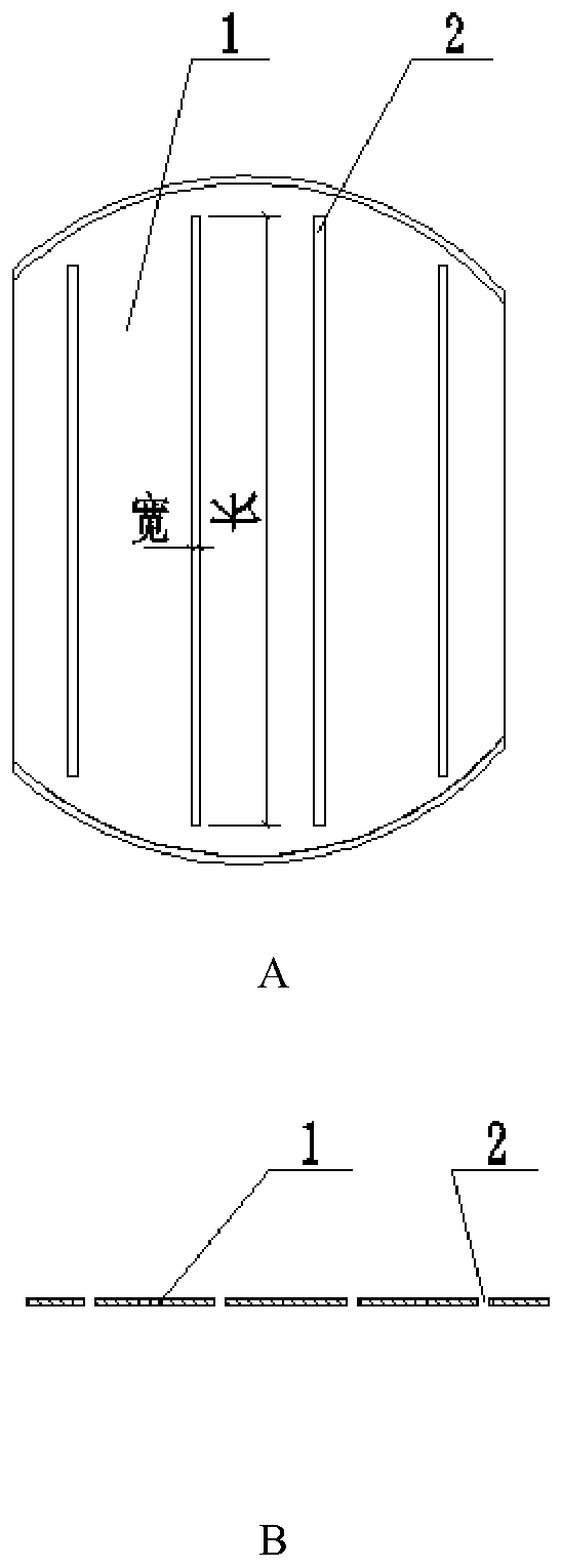
[0029] Such as figure 1 As shown, in one embodiment, the sieve of the distillation tray 1 provided by the present invention that can prevent distillation fouling is a bar-shaped sieve 2, and the width of the bar-shaped sieve 2 can be 2-20mm. The length of the shaped sieve 2 is adapted to the size of the tray, any two sieves are parallel, and the center distance between the sieves is between 30-80mm. The liquid to be deaminated moves horizontally from the left side of the figure to the right side, and the steam runs from the bottom of the tray to the top of the tray, and passes through the strip sieve holes. Heat transfer completes the deamination process.

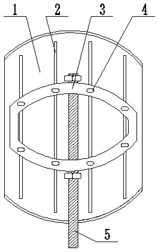
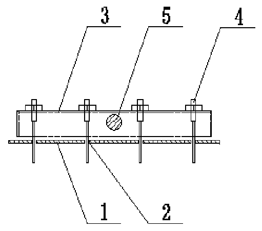
[0030] As shown in Figures 2 and 3, it contains the distillation trays that can prevent distillation fouling and a self-cleaning mechanism. The self-cleaning mechanism is a frame 3 that is rectangular or circular or has an arc or is only in the form of a bracket , such as an elliptical metal frame; the frame 3 is located ...

Embodiment 2

[0033] For a deammonization tower with a diameter of 350 mm, design a strip sieve hole and a self-cleaning mechanism with reference to Example 1. There are 4 strip sieves with a width of 3mm on the tray, the center distance of the strip sieves is 60mm, and the lengths of the strip sieves are 260mm, 310mm, 310mm, 260mm respectively; a 230mm width is set above the tray. Frame with circular arcs on both sides, the thickness of the frame is 30mm, the distance between the lower edge of the frame and the upper surface of the tray plate is 1mm; a metal sheet with a width of 2mm is connected to the frame, and the metal sheet is inserted into the bar-shaped sieve hole. The length of the metal sheet is (or depth) 75mm, the metal sheet completely penetrates the bar-shaped sieve hole, and there are two rows of metal sheets to ensure that the metal sheet can scrape the full length of the bar-shaped sieve hole when the frame is reciprocating; the frame is also connected with Shaft, the shaf...


PUM

PropertyMeasurementUnit
Widthaaaaaaaaaa

Abstract

The invention discloses a method and a device for preventing distillation scaling, and belongs to the fields of chemical industry and environmental protection. A tray with strip-shaped screen holes, provided in the invention, is combined with a self-cleaning mechanism, a frame connected with the shaft and protrusions connected with the frame reciprocatingly move along the strip-shaped screen holesunder the action of the cylinder in the running process of an ammonia distillation tower, the mechanical scraping action of the protrusions is used to remove scales adhered to the strip-shaped screenholes, and the scraped scales are powdery, flow with a liquid, and are finally discharged from the bottom of the tower; and the frame also removes scales adhered to the surface of the tray during reciprocating movement. The method and the device can be used for preventing the scaling problem in the distillation and deamination process of landfill leachate, anaerobic digestion liquids and other high-hardness and high-ammonia nitrogen wastewaters, and copper-ammonia complex and other metal-ammonia complex wastewaters.

Description

technical field [0001] The invention relates to a method and device for preventing distillation scaling, which is used to prevent waste water with high hardness such as landfill leachate and anaerobic digestion liquid, high ammonia nitrogen waste water and copper ammonium complex and other metal-ammonia complex waste water distillation deamination process The fouling problem belongs to the field of chemical industry and environmental protection. Background technique [0002] The first condition for the stable and continuous operation of the distillation column is that the mass transfer and heat transfer interface on the tray can function normally, for example, the sieve holes on the tray of the sieve tray are not blocked, or the float valve on the float valve tray can be normal. Open, close, or the valve hole on the bubble-cap tray is not blocked, etc., to ensure that the steam can penetrate the tray layer by layer and move from the bottom of the tower to the top of the towe...

Claims


Application Information

Patent Timeline
IPC IPC(8): B01D3/14B01D3/22B08B1/00
CPCY02P10/20
Inventor 李祖强张建华段文龙高富宝张勇
Owner JIANGSU WODEKAI ENVIRONMENTAL PROTECTION TECH CO LTD
Learn More