
Gas-liquid countercurrent two-stage hydrocracking method

A hydrocracking and countercurrent technology, which is applied in hydroprocessing process, petroleum industry, and hydrocarbon oil treatment, etc., to reduce the amount of cold hydrogen, improve economic benefits, and improve the effect of temperature matching

Active Publication Date: 2019-05-21
CHINA PETROLEUM & CHEM CORP +1
View PDF11 Cites 7 Cited by
  • Summary
  • Abstract
  • Description
  • Claims
  • Application Information

AI Technical Summary

Problems solved by technology

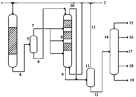
[0011] Aiming at the deficiencies of the prior art, the present invention provides a gas-liquid countercurrent two-stage hydrocracking method, which can effectively solve the problem of temperature matching between refining and cracking reactors, reduce the amount of cold hydrogen at the inlet of the cracking reactor, and at the same time Improve naphtha yield

Method used


Image

  • Gas-liquid countercurrent two-stage hydrocracking method
  • Gas-liquid countercurrent two-stage hydrocracking method
  • Gas-liquid countercurrent two-stage hydrocracking method

Examples


Embodiment 1

[0035] Using the process flow of the present invention, vacuum wax oil is used as the raw material, the openings of the cold hydrogen valves at the inlets of the second, third and fourth beds of the cracking section are the same, the volume flow ratio is 1:1:1, and the ammonia gas returned to the beds Concentrations were the same and no control was performed.

Embodiment 2

[0037] Adopting the technological process of the present invention, using vacuum wax oil as raw material, the openings of the cold hydrogen valves at the inlets of the second, third and fourth beds of the cracking section are successively reduced, and the volume flow ratio is 1.5:1.2:1, and the ammonia returned to the beds The gas concentrations are the same and are not controlled.

Embodiment 3

[0039] Using the process flow of the present invention, vacuum wax oil is used as the raw material, the openings of the cold hydrogen valves at the inlets of the second, third and fourth beds of the cracking section are the same, and the volume flow ratio is 1:1:1. The contents of ammonia in the gas phase of the four beds are 0.03v%, 0.6v%, and 0.12v% in turn.

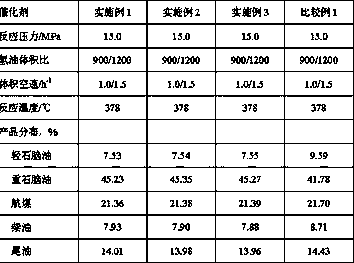
[0040] Table 2 Main process conditions and product distribution of hydrocracking

[0041]

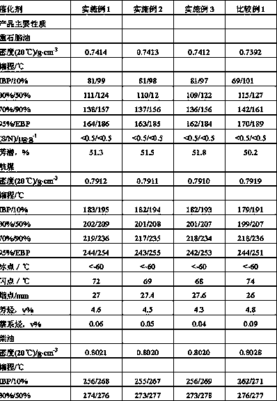
[0042] Table 3 Main properties of the product

[0043]

[0044] It can be seen from the examples that the vacuum gas oil can effectively reduce the amount of cold hydrogen at the cracking reactor inlet under the same conversion depth through this technology, and can increase the production of heavy naphtha by the largest amount while reducing the energy consumption of the device , Improve product properties.


PUM


Abstract

The invention discloses a gas-liquid countercurrent two-stage hydrocracking method, which comprises the following steps: (1) using a fixed bed reactor, mixing feedstock oil with hydrogen, then firstlyenabling the mixture to enter a hydrofining reactor for carrying out desulfurization, denitrification and an aromatic hydrocarbon saturation reaction, and then enabling effluent to enter a flash tankso as to be subjected to gas-liquid separation; (2) enabling new hydrogen to enter a hydrocracking reactor from the bottom of the hydrocracking reactor, and enabling liquid phase effluent, obtained after separation of the flash tank, to enter the hydrocracking reactor from the top of the hydrocracking reactor so as to be subjected to a hydrocracking reaction, and enabling gas phase, obtained after separation of the flash tank, to separately enter different bed layer inlets of the hydrocracking reactor; (3) enabling effluent of the hydrocracking reactor to enter a separation system so as to besubjected to gas-liquid separation, recycling the separated gas as supplemental hydrogen, enabling the liquid phase product to enter a fractionating tower so as to be separated, carrying out fractionation in a the fractionating tower to obtain naphtha, jet fuel, diesel oil and tail oil. The method can effectively solve the problem of temperature matching of the refining and cracking reactors, reduces the consumption of cold hydrogen at an entrance of the cracking reactor, and increases the yield of the naphtha.

Description

technical field [0001] The invention relates to a gas-liquid countercurrent two-stage hydrocracking method, in particular to a gas-liquid countercurrent two-stage hydrocracking method for increasing naphtha yield. Background technique [0002] Hydrocracking technology has the characteristics of strong adaptability to raw materials, great flexibility in production operations and product plans, and good product quality. It can directly convert various heavy and low-quality feedstocks into high-quality jet fuel, diesel, and lubricating oil base materials that are urgently needed by the market. As well as chemical naphtha and tail oil steam cracking raw materials for ethylene production, it has become one of the most important heavy oil deep processing processes in modern oil refining and petrochemical industries, and has been increasingly widely used at home and abroad. With the increasing maturity of hydrocracking technology in my country, reducing the energy consumption of hy...

Claims


Application Information

Patent Timeline
IPC IPC(8): C10G67/02
Inventor 崔哲王仲义孙士可吴子明
Owner CHINA PETROLEUM & CHEM CORP
Learn More