Catalytic diesel oil combined treatment process and treatment system

A technology for catalyzing diesel oil and treatment process, which is applied in hydrotreating process, hydrocarbon oil treatment, petroleum industry, etc. It can solve the problems of strong heat release, short operation period of the device, and low yield, so as to reduce the amount of cold hydrogen and reduce the Operation cost and effect of improving economy

Pending Publication Date: 2022-07-19
CHINA PETROLEUM & CHEM CORP +1
View PDF5 Cites 0 Cited by
  • Summary
  • Abstract
  • Description
  • Claims
  • Application Information

AI Technical Summary

Problems solved by technology

[0004] Aiming at the deficiencies in the prior art, the purpose of the present invention is to provide a combined catalytic diesel oil treatment process and treatment system, which separates different hydrocarbon components of catalytic diesel oil from the molecular refining level, and simultaneously matches The combined process of pretreatment, distillation and hydrogenation processes different types of aromatics in catalytic diesel according to their respective appropriate reaction paths, and solves the hydroconversion process caused by the high content of aromatics in catalytic diesel and the large difference in hydrogenation conversion rules due to complex composition Medium and strong exothermic, easy to generate hot spots, difficult to control the reaction process, poor product quality, low yield and short operation period of the device, to achieve reasonable and efficient conversion of various components of catalytic diesel, greatly reduce hydrogen consumption, and improve the quality of high value-added aromatics products The significant increase in yield and yield is of vital significance to ensure the long-term operation of the unit and greatly promote the improvement of refinery quality and efficiency

Method used


Image

  • Catalytic diesel oil combined treatment process and treatment system
  • Catalytic diesel oil combined treatment process and treatment system
  • Catalytic diesel oil combined treatment process and treatment system

Examples


Embodiment 1

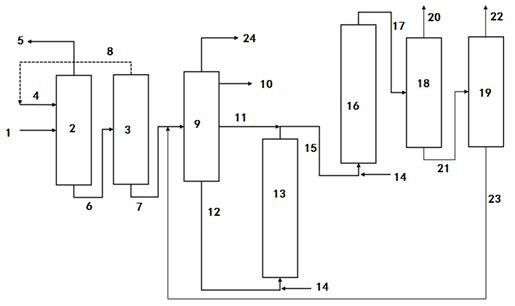
[0047] This embodiment adopts figure 1 As shown in the process flow, the catalytic diesel oil enters the pretreatment unit, wherein the pretreatment unit is an aromatic hydrocarbon extraction device, the extraction agent is sulfolane, the extraction temperature is 170 ° C, and the mass ratio of the agent to oil is 15.0; after extraction, the rich aromatic hydrocarbon components enter the fractionation unit, light The dry point temperatures of the distillate and middle distillate were 220°C and 310°C, respectively. The first and second fluidized bed reaction zones use the same hydrogenation catalyst. The hydrogenation catalyst is the one developed by the Dalian Petrochemical Research Institute of China Petroleum & Chemical Co., Ltd. FC-70 catalyst, wherein the hydrogenation catalyst used in the second fluidized bed reaction zone is the catalyst after the first fluidized bed reaction zone has been operated for 3 months; the temperature of the first fluidized bed hydrogenation re...

Embodiment 2

[0049] This embodiment adopts figure 1 As shown in the process flow, the catalytic diesel oil enters the pretreatment unit, wherein the pretreatment unit is set as an aromatic hydrocarbon extraction device, N-methylpyrrolidone is selected as the extraction agent, the extraction temperature is 150 ° C, and the mass ratio of the agent to oil is 10.0; The fractions enter the fractionation unit, and the dry point temperatures of the light and middle fractions are 180°C and 290°C, respectively. The first and second ebullated bed reaction zones use the same hydrogenation catalyst, and the hydrogenation catalyst is the one that has been crushed (broken into short strips of 0.5-1.0mm) and developed by Dalian Petrochemical Research Institute of China Petroleum & Chemical Co., Ltd. FC-70 catalyst; the temperature of the first fluidized bed hydrogenation reaction zone is 410 °C, the reaction pressure is 12.0 MPa, the hydrogen-oil ratio is 700, and the liquid hourly volume space velocity ...

Embodiment 3

[0051] Basically the same as Example 1, the difference is that the extraction agent of the pretreatment unit is [emim]N(CN)2, the extraction temperature is 40 ° C, and the mass ratio of the agent to oil is 10; and the dry point temperatures of the middle distillate are 180°C and 290°C, respectively. The first and second fluidized bed reaction zones use the same hydrogenation catalyst. The hydrogenation catalyst is the one developed by the Dalian Petrochemical Research Institute of China Petroleum & Chemical Co., Ltd. FC-70 catalyst; the temperature of the first fluidized bed hydrogenation reaction zone is 410 °C, the reaction pressure is 12.0 MPa, the hydrogen-oil ratio is 700, and the liquid hourly volume space velocity is 1.0 h -1 ; The temperature of the second fluidized bed hydrogenation reaction zone is 425 °C, the reaction pressure is 12.0 MPa, the hydrogen-oil ratio is 700, and the liquid hourly volume space velocity is 0.5 h. -1 ; The specific test results are shown i...


PUM


Abstract

The invention discloses a catalytic diesel oil combined treatment process and treatment system. The system comprises a pretreatment unit, a pretreatment agent recovery unit, a fractionation unit, a first fluidized bed hydrogenation reaction zone, a second fluidized bed hydrogenation reaction zone and a separation unit, the catalytic diesel oil is treated by the system to obtain a light fraction product with monocyclic aromatic hydrocarbon as a main component. The technical problems of strong heat release, easiness in generation of hot spots, difficulty in control of a reaction process, poor product quality, low yield and short device operation period in a hydro-conversion process caused by high aromatic hydrocarbon content, complex composition and large hydro-conversion rule difference of the catalytic diesel oil are solved, reasonable and efficient conversion of each component of the catalytic diesel oil is realized, the hydrogen consumption is greatly reduced, and the production cost is reduced. The quality and yield of high-added-value aromatic hydrocarbon products are remarkably improved, long-period operation of the device is improved, and quality improvement and efficiency improvement of a refinery plant are greatly promoted.

Description

technical field [0001] The invention belongs to the technical field of petrochemical industry, and particularly relates to a high-efficiency conversion process for catalyzing diesel oil. Background technique [0002] Catalytic cracking technology is one of the most important technical means to lighten heavy oil and occupies an important position in the oil refining industry. However, refineries face many problems when processing inferior catalytic diesel, especially the high content of aromatic hydrocarbons, and the content of polycyclic aromatic hydrocarbons is as high as 60%. The catalytic diesel hydrogenation technology for inferior high aromatic hydrocarbons can be divided into hydrorefining technology, hydroupgrading technology, hydrocracking technology and hydroconversion technology according to different production purposes. Hydrotreating technologies mainly include UOP's MQD (Maximumquality distillate) combined refining technology, SynSat process technology, Prime-D...

Claims


Application Information

Patent Timeline
IPC IPC(8): C10G67/00
CPCC10G67/00C10G2300/4006C10G2300/4012C10G2300/4018C10G2300/44C10G2300/70Y02P30/20
Inventor 仝玉军杨涛葛海龙孟兆会刘玲张文芳
Owner CHINA PETROLEUM & CHEM CORP
Why Eureka
Try Eureka