
Experimental device for simulating blending of engine and simulation method thereof

A technology of experimental device and simulation method, applied in the direction of engine test, measurement device, machine/structural component test, etc., can solve the problem of restricting the development of optimal design of engine configuration, lack of economical and effective experimental methods, and high cost of thermal engine prototypes. problem, to achieve the effect of small footprint, reduced experimental cost, and simple structure

Active Publication Date: 2019-05-21
XI AN JIAOTONG UNIV
View PDF7 Cites 1 Cited by
  • Summary
  • Abstract
  • Description
  • Claims
  • Application Information

AI Technical Summary

Problems solved by technology

The mixing of liquid jets and cross-flows mainly includes processes such as atomization of liquids, droplet diffusion and evaporation, and vortex entrainment and entrainment. It has nonlinear and multi-scale characteristics, and there are still challenges in theoretical analysis and complete numerical calculations; experimental research It is the basis for understanding the mechanism and law of gas-liquid two-phase mixing in the above process. Conventional laboratory conditions are usually difficult to simulate the high-temperature and high-pressure environment of the actual engine mixing process, and the cost of heat engine prototype experiments is high. The measurement of field parameters brings great difficulties
At present, there is still a lack of economical and effective experimental methods for the above-mentioned processes in actual engines, which restricts the development of jet mixing gas-liquid two-phase flow process organization technology in engines and the optimal design of engine configurations.

Method used


Image

  • Experimental device for simulating blending of engine and simulation method thereof
  • Experimental device for simulating blending of engine and simulation method thereof
  • Experimental device for simulating blending of engine and simulation method thereof

Examples


Embodiment 1

[0051] A thermal power engine uses water and high-temperature gas for mixing. The mixing chamber structure is a rectangular cavity with a cross-sectional size of 95×95mm and a length of 550mm. The pressure of the mixing chamber is 2.5MPa, the gas temperature is 1500K, and the gas mass flow rate is 0.92kg. / s, gas density 5.36kg / m 3 , the water-fuel ratio is 1.0, the atomized particle size D32 of water is 120um, the initial droplet velocity is 22m / s, and the nozzle atomization cone angle is 80°. Using the modeling method proposed in this paper, acetone and heated air are used for mixing in the modeling experiment. The structural size of the mixing chamber is the same as that of the engine mixing chamber (cross-sectional size 95×95mm, length 550mm), and the pressure of the mixing chamber is 0.1 MPa, heating air temperature is 573K, air velocity is 26m / s, acetone atomized droplet D32 is 40μm, initial velocity is 20m / s, acetone mass flow rate is 0.2kg / s, according to acetone atomi...


PUM


Abstract

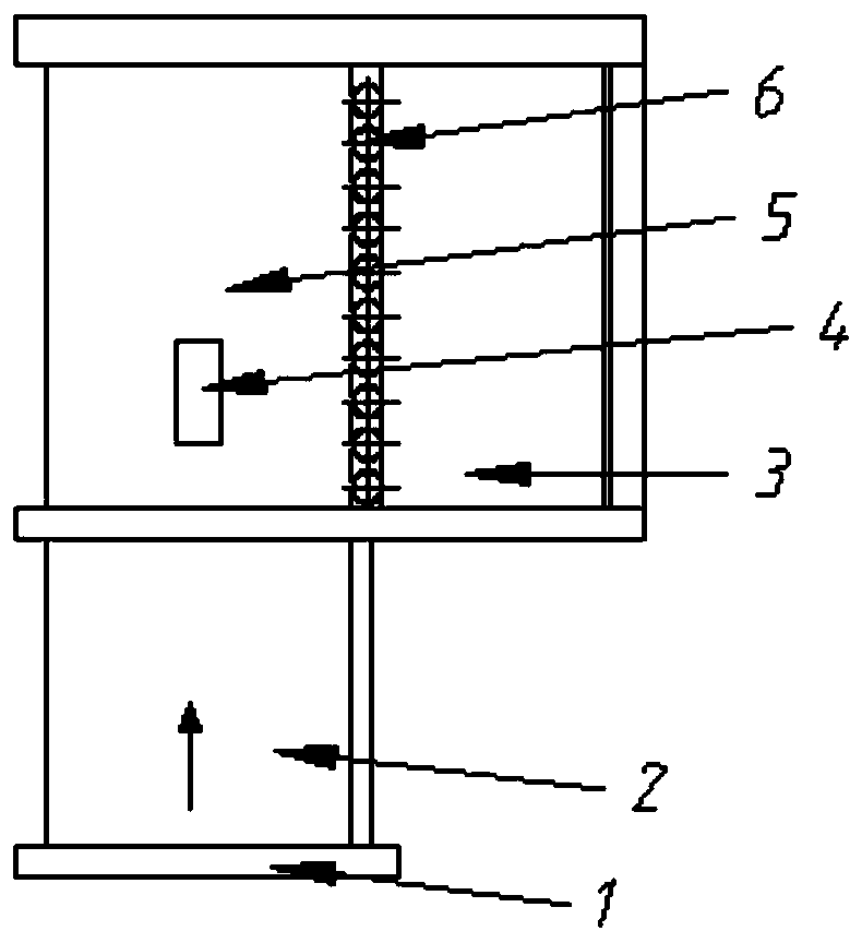
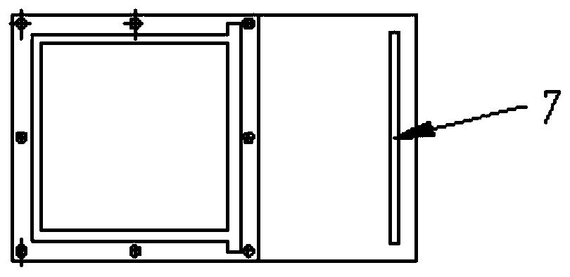
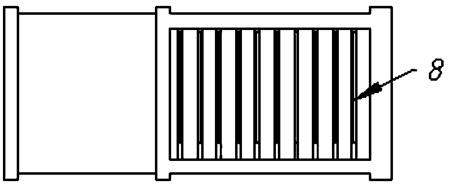
The invention discloses an experimental device for simulating blending of an engine, comprising a mainstream gas inlet section, wherein the mainstream gas inlet section communicates with a blending test section; the blending test section is provided with a nozzle mounting port, a row of cylindrical holes for mounting metal cylindrical rods are formed in the wall surface of one side of the blendingtest section, a closed space extending outwards is further formed in the side of the blending test section, and a first track for mounting transparent glass is arranged on the surface, opposite to the side surface where the cylindrical holes are formed, of the closed space; a second track for mounting a temperature measuring plate is arranged at an outlet of the blending test section; and perspective seams are formed in the side faces of the metal cylindrical rods. The invention further discloses a simulation method of the experimental device for simulating blending of the engine. According to the device, high-power heating and pressurizing equipment is not needed, and visual measurement can be achieved.

Description

technical field [0001] The invention belongs to the technical field of engine jet mixing, in particular to an experimental device and a simulation method for simulating engine mixing. Background technique [0002] The mixing of liquid jet and lateral airflow is an important way to enhance gas-liquid flow and heat transfer. It is widely used in industrial and national defense fields, such as liquid fuel combustion in aero-engines, turbojet engine inlet jet pre-cooling, large-scale The exhaust flame cooling process of the thrust rocket. The mixing of liquid jets and cross-flows mainly includes processes such as atomization of liquids, droplet diffusion and evaporation, and vortex entrainment and entrainment. It has nonlinear and multi-scale characteristics, and there are still challenges in theoretical analysis and complete numerical calculations; experimental research It is the basis for understanding the mechanism and law of gas-liquid two-phase mixing in the above process....

Claims


Application Information

Patent Timeline
Patent Type & Authority Applications(China)
IPC IPC(8): G01M15/00
Inventor 张海滨白博峰裴焕
Owner XI AN JIAOTONG UNIV
Learn More