
Hybrid zinc-nickel redox flow battery

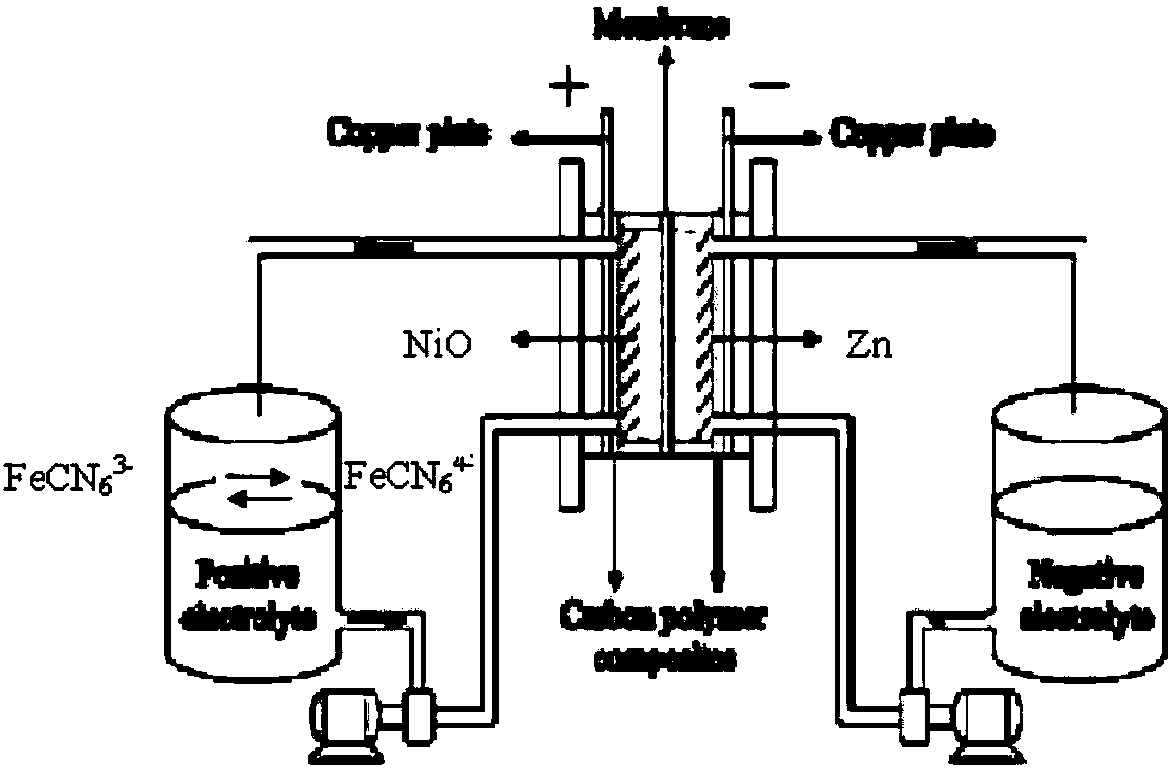
A flow battery and hybrid technology, which can be used in regenerative fuel cells and other directions, can solve the problems of low solid-phase electrode surface capacity and difficulty in meeting the capacity requirements of large-scale energy storage batteries.

Active Publication Date: 2019-05-21
DALIAN INST OF CHEM PHYSICS CHINESE ACAD OF SCI +1
View PDF5 Cites 3 Cited by
  • Summary
  • Abstract
  • Description
  • Claims
  • Application Information

AI Technical Summary

Problems solved by technology

[0005] The positive pole of the zinc-nickel flow battery is nickel oxide, which belongs to the solid-solid phase conversion process. The surface capacity of the solid-phase electrode is low, and it is difficult to meet the capacity requirements of large-scale energy storage batteries.

Method used


Image

  • Hybrid zinc-nickel redox flow battery
  • Hybrid zinc-nickel redox flow battery

Examples


Embodiment 1

[0021] Hybrid zinc-nickel flow battery:

[0022] 1) The positive electrode uses a 5*5cm NiO electrode;

[0023] 2) The negative electrode uses 5*5cm carbon felt (5mm thickness) and 5*5cm zinc sheet (1mm thickness);

[0024] 3) Use 30 mL of 0.2 mol / L potassium ferrocyanide in 3 mol / L potassium hydroxide solution as the positive electrode electrolyte;

[0025] 4) Negative electrode electrolyte adopts 3mol / L potassium hydroxide solution of 0.5mol / L zinc ion of 30mL;

[0026] 5) The diaphragm adopts cationic membrane Nafion115;

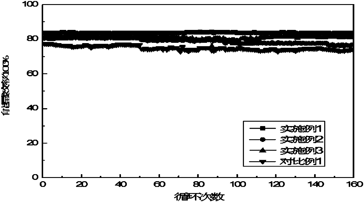
[0027] 6) Battery at 40mA / cm 2 Under charge and discharge, charging time: 1h, discharge cut-off voltage: 1.0V.

Embodiment 2

[0029] Hybrid zinc-nickel flow battery:

[0030] 1) The positive electrode uses a 5*5cm NiO electrode;

[0031] 2) The negative electrode uses 5*5cm carbon felt (5mm thickness) and 5*5cm zinc sheet (1mm thickness);

[0032] 3) The positive electrode electrolyte is 30 mL of 8 mol / L potassium hydroxide solution of 0.5 mol / L potassium ferrocyanide;

[0033] 4) Negative electrode electrolyte adopts 8mol / L potassium hydroxide solution of 0.8mol / L zinc ion of 30mL;

[0034] 5) The diaphragm adopts cationic membrane Nafion115;

[0035] 6) Battery at 40mA / cm 2 Under charge and discharge, charging time: 1h, discharge cut-off voltage: 1.0V.

Embodiment 3

[0037] Hybrid zinc-nickel flow battery:

[0038] 1) The positive electrode uses a 5*5cm NiO electrode;

[0039] 2) The negative electrode uses 5*5cm carbon felt (5mm thickness) and 5*5cm zinc sheet (1mm thickness);

[0040] 3) The positive electrode electrolyte adopts 30mL of 6mol / L potassium hydroxide solution of 1mol / L potassium ferrocyanide;

[0041] 4) Negative electrode electrolyte adopts 6mol / L potassium hydroxide solution of 0.1mol / L zinc ion of 30mL;

[0042] 5) The diaphragm adopts cationic membrane Nafion115;

[0043] 6) Battery at 40mA / cm 2 Under charge and discharge, charging time: 1h, discharge cut-off voltage: 1.0V.


PUM


Abstract

A hybrid zinc-nickel redox flow battery is in a way that a positive electrode is a NiO electrode, a negative electrode is a carbon felt or / and a zinc electrode, a positive electrolyte employs a ferrous cyanide ion alkali solution, and a negative electrolyte employs a zinc ion alkali solution; during charging, the positive electrode generate oxidization reaction from ferrous cyanide ion to cyanideiron ion, NiO gradually participates in electrochemical current formation reaction to generate NiOOH, and negative generates zinc ion deposition reaction; and during discharging, the positive electrode generates oxidization reaction from NiOOH to NiO, the cyanide iron ion gradually participates in electrochemical current formation reaction with consumption of NiOOh to generate ferrous cyanide ion,and the negative electrode generates elemental zinc dissolution reaction. Aiming at the problem of capacity limitation of a zinc-nickel redox flow battery positive electrode, the hybrid zinc-nickel redox flow battery is provided and is used for improving energy storage capacity of the zinc-nickel redox flow battery; and meanwhile, with the addition of the cyanide iron ion, the cycle stability ofthe zinc-nickel redox flow battery positive electrode can be improved.

Description

technical field [0001] The invention relates to a zinc-nickel flow battery. Background technique [0002] As the world's energy consumption demand continues to grow, exploitable petroleum resources are increasingly depleted, while environmental pollution is becoming more serious, how to solve the increasing energy demand for global economic development and the aggravation of environmental pollution has become a global problem. Therefore, countries around the world are paying more and more attention to the storage and reuse of clean energy such as wind energy and solar energy, and the research on accelerating the replacement of fuel vehicles by electric vehicles. [0003] Zinc-nickel flow battery is a new type of low-cost, high-efficiency, and environment-friendly flow energy storage battery. It has the advantages of high energy density and current efficiency, simple and easy operation of the device, long service life, and low cost. Its main application It is widely used in ...

Claims


Application Information

Patent Timeline
IPC IPC(8): H01M8/18
CPCY02E60/50
Inventor 赖勤志李先锋张华民宋杨许鹏程刘新运郑建伟
Owner DALIAN INST OF CHEM PHYSICS CHINESE ACAD OF SCI
Learn More