
Optical microimaging device and method based on line scanning temporal-spatial focusing

A microscopic imaging and line scanning technology, applied in the optical field, can solve the problems of signal crosstalk and limited imaging depth, and achieve the effect of wide field of view, high temporal resolution, and suppressing signal crosstalk.

Inactive Publication Date: 2019-05-24
TSINGHUA UNIV
View PDF5 Cites 5 Cited by
  • Summary
  • Abstract
  • Description
  • Claims
  • Application Information

AI Technical Summary

Problems solved by technology

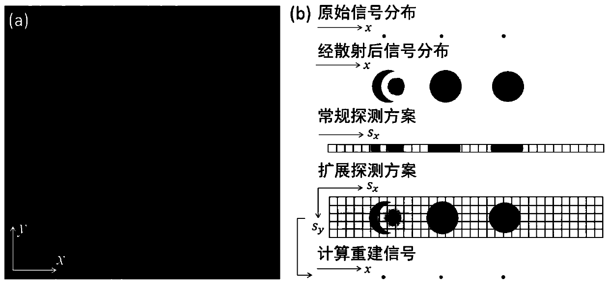
It should be pointed out that although spatio-temporal focusing microscopy achieves wide-field tomographic excitation of deep tissue based on nonlinear optical effects, the excited optical signal will still be affected by tissue scattering, resulting in signal crosstalk. Imaging depth will still be limited when probing

Method used


Image

  • Optical microimaging device and method based on line scanning temporal-spatial focusing
  • Optical microimaging device and method based on line scanning temporal-spatial focusing
  • Optical microimaging device and method based on line scanning temporal-spatial focusing

Examples


Embodiment Construction

[0027] In order to make the purpose, technical solutions and advantages of the embodiments of the present invention clearer, the technical solutions in the embodiments of the present invention will be clearly and completely described below in conjunction with the drawings in the embodiments of the present invention. Obviously, the described embodiments It is a part of embodiments of the present invention, but not all embodiments. Based on the embodiments of the present invention, all other embodiments obtained by persons of ordinary skill in the art without creative efforts fall within the protection scope of the present invention.

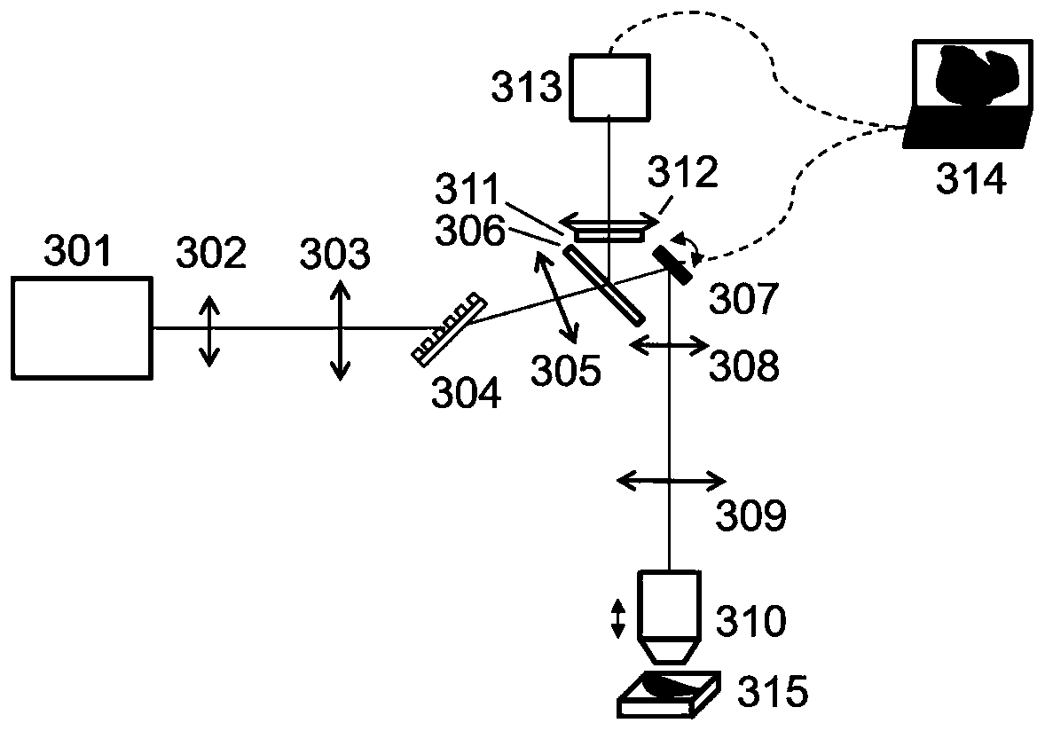
[0028] figure 1 It is a schematic structural diagram of an optical microscopic imaging device based on line-scanning spatio-temporal focusing according to an embodiment of the present invention, as shown in figure 1 As shown, the device includes: a laser emitting module 101, a line scanning module 102, an optical microscope module 103, a synchron...


PUM


Abstract

An embodiment of the invention provides an optical microimaging device and method based on line scanning temporal-spatial focusing. The device comprises a laser transmitting module, a line scanning module, an optical microscopic module, a synchronous filtering module and a reconstruction module, the laser transmitting module generates nonlinear excitation pulse light, the line scanning module acquires angular dispersion and deflection angle of the excitation pulse light and enables the excitation pulse light to scan a sample, the optical microscopic module forms a focusing line focusing on twodimensions like space and time at the same time in the sample to excite the sample on the basis of nonlinear optical effect to generate a transmitting light signal; the synchronous filtering module detects the transmitting light signal of the sample and filters the transmitting light signal, and the reconstruction module performs two-dimension reconstruction according to the transmitting light signal detected by the synchronous filtering module to acquire a reconstruction image of the sample. The optical microimaging device can effectively inhibit signal crosstalk caused by stray light, has the advantages of wide field of view, high spatial resolution, high temporal resolution and high penetration depth and can provide rich information for biological dynamic process study and disease diagnosis basis.

Description

technical field [0001] Embodiments of the present invention relate to the field of optical technology, and in particular to an optical microscopic imaging device and method based on line-scan spatio-temporal focusing. Background technique [0002] Optical microscopy imaging has the advantages of non-invasive, high sensitivity, high resolution, and flexible imaging scale, and has become an essential technical means for biomedical research. At present, optical microscopic imaging has not only been used in the study of biological dynamic processes, but also in many fields such as clinical disease diagnosis. However, due to the anisotropy and inhomogeneity of biological tissue, light will undergo random refraction and scattering when propagating in biological tissue, causing signal crosstalk and reducing the signal-to-noise ratio of imaging. [0003] In order to overcome the influence of biological tissue scattering, laser scanning confocal microscopy technology has been develo...

Claims


Application Information

Patent Timeline
IPC IPC(8): G02B21/00
Inventor 孔令杰张元龙周天贶谢浩戴琼海
Owner TSINGHUA UNIV
Learn More