A Broadband Microstrip Reflect Array Antenna

A reflectarray antenna and microstrip technology, applied in the field of communication, can solve problems such as low bandwidth, large cross-polarization, and complex structure, and achieve the effects of overcoming narrow bandwidth, wide gain bandwidth, and large cross-polarization

Active Publication Date: 2020-08-04
XIDIAN UNIV
View PDF9 Cites 0 Cited by
  • Summary
  • Abstract
  • Description
  • Claims
  • Application Information

AI Technical Summary

Problems solved by technology

[0008] The purpose of the present invention is to propose a broadband microstrip reflectarray antenna to solve the technical problems of complex structure, low bandwidth and large cross polarization in the prior art.

Method used


Image

  • A Broadband Microstrip Reflect Array Antenna
  • A Broadband Microstrip Reflect Array Antenna
  • A Broadband Microstrip Reflect Array Antenna

Examples


Embodiment 1

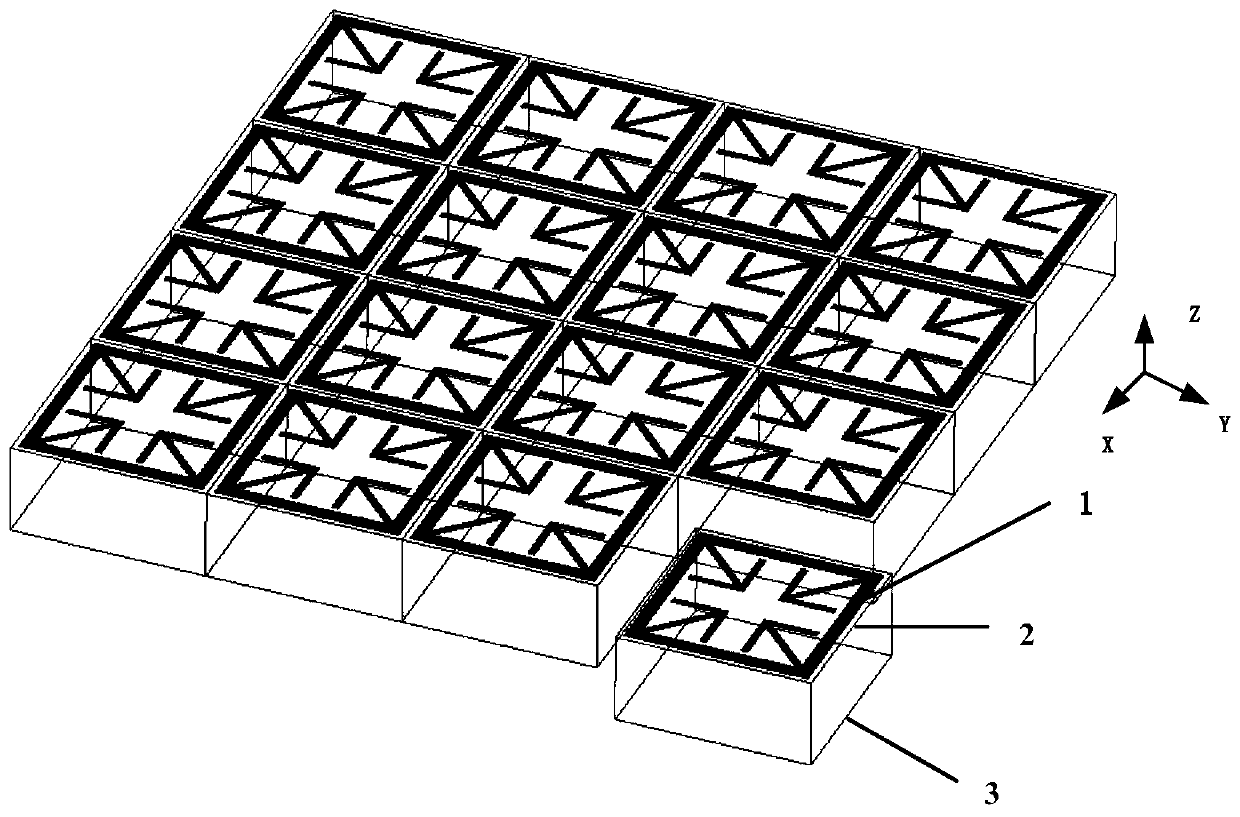
[0026] refer to figure 1 , figure 2 and image 3

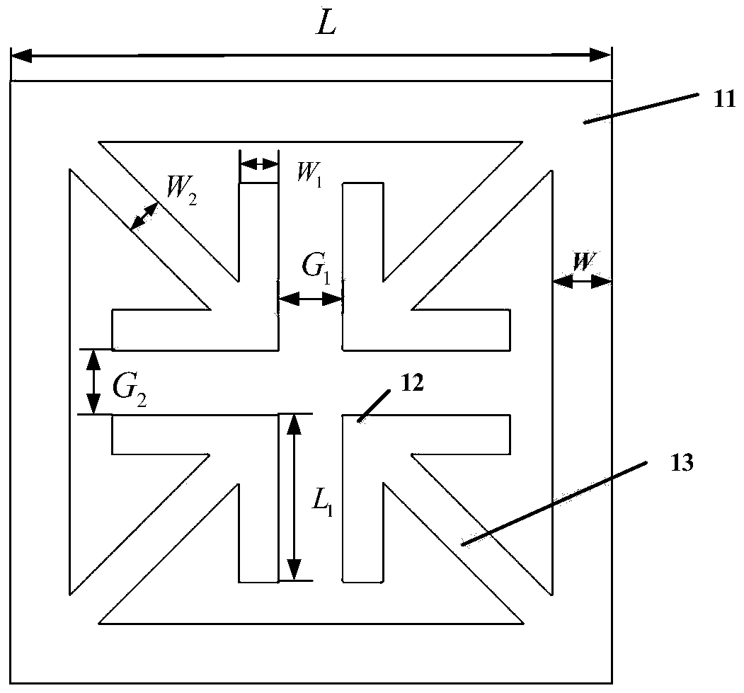
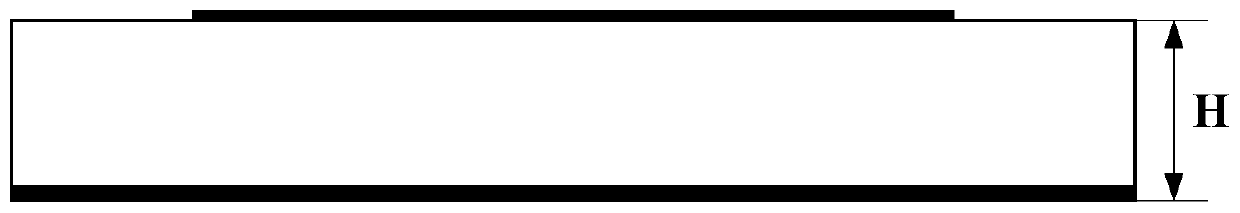
[0027] A broadband microstrip reflectarray antenna, including M×N radiating units arranged periodically, wherein, M≥2, N≥2, M and N are positive integers; each radiating unit sequentially includes from top to bottom: A microstrip patch 1, a dielectric substrate 2, and a metal floor 3; it is characterized in that: the microstrip patch 1 is composed of a square ring patch 11, four L-shaped vibrators 12 and four inclined vibrators 13, the square The annular patch 11 is located on the inner side of the upper surface of the dielectric substrate 2 of the radiation unit, and the four L-shaped vibrators 12 are located in the square annular patch 11, and are distributed symmetrically about the Z axis of the center of the radiation unit; the four inclined vibrators 13 One end of the four L-shaped vibrator 12 is connected to the right angle formed by the square ring patch 11, and the other end is connected to the angle formed by the ...

Embodiment 2

[0037] The arrangement period of each radiation unit is D, where D is 0.25λ˜0.35λ, and λ is the wavelength. When D=0.25λ, D=2.7mm

[0038] The side length of the square ring patch is L, and the variation range of the reflection phase of the radiation unit can be determined by adjusting the side length L of the square ring patch; the width of the square ring patch 11 is W, wherein W is 0.01λ~0.03 λ; when W=0.01λ, W=0.1mm.

[0039] The width of the L-shaped vibrator (12) is W 1 , the W 1 is the k of the width W of the square annular patch (11) 1 times, ie W 1 =k 1 *W, where k 1 The value range is 0.4 to 0.6; the length of the L-shaped vibrator (12) is L 1 , the L 1 It is 0.3 times of the length L of the square annular patch (11), that is, L 1 =0.3*L; the distances between the L-shaped oscillators (12) in the horizontal and vertical directions are G respectively 1 and G 2 , where G 1 =G 2 , G 1 =0.3*(L-2*W). when k 1 =0.4, namely W 1 =0.4*W,W 1 = 0.04 mm.

[00...

Embodiment 3

[0043] The arrangement period of each radiation unit is D, where D is 0.25λ˜0.35λ, and λ is the wavelength. When D=0.35λ, D=3.5mm

[0044] The side length of the square ring patch is L, and the variation range of the reflection phase of the radiation unit can be determined by adjusting the side length L of the square ring patch; the width of the square ring patch 11 is W, wherein W is 0.01λ~0.03 λ; when W=0.03λ, W=0.3mm.

[0045] The width of the L-shaped vibrator (12) is W 1 , the W 1 is the k of the width W of the square annular patch (11) 1 times, ie W 1 =k 1 *W, where k 1 The value range is 0.4 to 0.6; the length of the L-shaped vibrator (12) is L 1 , the L 1 It is 0.3 times of the length L of the square annular patch (11), that is, L 1 =0.3*L; the distances between the L-shaped oscillators (12) in the horizontal and vertical directions are G respectively 1 and G 2 , where G 1 =G 2 , G 1 =0.3*(L-2*W). when k 1 =0.6, namely W 1 =0.6*W,W 1 = 0.18 mm.

[00...


PUM


Abstract

The invention discloses a broadband microstrip reflective array antenna which mainly solves the technical problem of the complex structure and the narrow bandwidth in the prior art. The microstrip reflective array antenna comprises M*N radiating elements arranged periodically, wherein M*N, M>=2, N>=2, M and N are positive integers. Each radiating element includes, in order from top to bottom, a microstrip patch, a dielectric substrate, and a metal floor. The microstrip patch is composed of a square ring patch, four L-shaped vibrators and four tilted vibrators. The square ring patch is locatedon the inner side of the upper surface of the dielectric substrate of the radiating element. The four L-shaped vibrators are located in the square ring patch and are distributed symmetrically about the Z-axis of the center of the radiating element. One end of each of the four tilted vibrators is connected to the right angle formed by the square ring patch, and the other end each of the four tiltedvibrators is connected to an intersection angle at the joint of the L-shaped vibrators. The broadband microstrip reflective array antenna is increased in gain bandwidth, has a simple structure and good main polarization characteristics, and can be applied to electromagnetic wave regulation in a microwave band.

Description

technical field [0001] The invention belongs to the technical field of communication, and in particular relates to a broadband microstrip reflective array antenna in the technical field of electromagnetic communication, which can be used for electromagnetic wave control in microwave bands. Background technique [0002] In recent years, with the rapid development of mobile communication technology, both radar and communication systems expect antennas to have more functionality and adaptability. Microstrip antennas have been widely studied and applied due to their small size, light weight, low profile, and easy integration. Microstrip reflectarray antennas have some advantages of reflector antennas and large phased array antennas, and have been favored by researchers. favor. [0003] The earliest reflectarray antenna concept was proposed by Berry, Malech and Kenndey in 1963 based on the open-short waveguide reflectarray, which can realize polarization conversion, polarization...

Claims


Application Information

Patent Timeline
Patent Type & Authority Patents(China)
IPC IPC(8): H01Q21/06
Inventor 李龙方遥李美玲易浩刘海霞
Owner XIDIAN UNIV
Why Eureka
Try Eureka