Eureka AIR delivers breakthrough ideas for toughest innovation challenges, trusted by R&D personnel around the world.

Layer-by-layer heating device for cylindrical bevel gears and method thereof

A technology of cylindrical helical gears and heating devices, applied in the field of heat treatment, can solve the problems of reduced gear quality and service life, uneven quenching hardness of tooth surfaces, uneven heating of tooth surfaces, etc., to reduce influence, reduce tooth profile temperature difference, Even heating effect

Active Publication Date: 2019-05-31
TAICANG FANSHENG ELECTRONICS TECH CO LTD
View PDF5 Cites 8 Cited by
  • Summary
  • Abstract
  • Description
  • Claims
  • Application Information

AI Technical Summary

Problems solved by technology

In the prior art, when the cylindrical helical gear is heated by induction, the magnetic field generated by the traditional circular induction coil cannot be kept perpendicular to the tooth surface of the cylindrical helical gear, and the tooth surface is heated unevenly, and the tooth top is prone to overheating and the tooth groove is not. In the case of hardened layers, the resulting cylindrical helical gear tooth flanks often have defects, which reduce the quality and service life of the gear
In addition, due to the end face effect, during the movement of the circular induction coil, the cylindrical helical gear is affected by the comprehensive electromagnetic effect at the inlet and outlet positions of the induction coil, and it is easy to generate a large temperature difference on the tooth profile, resulting in uneven quenching hardness of the tooth surface The phenomenon, that is, the appearance of soft and hard points

Method used


Image

  • Layer-by-layer heating device for cylindrical bevel gears and method thereof
  • Layer-by-layer heating device for cylindrical bevel gears and method thereof
  • Layer-by-layer heating device for cylindrical bevel gears and method thereof

Examples


Embodiment Construction

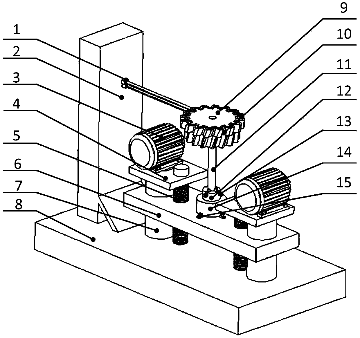
[0038] The specific embodiments of the present invention will be described in detail below in conjunction with the accompanying drawings, instead of limiting the protection scope of the present invention. It should be understood that in the description of the present invention, the directions or positional relationships indicated by the terms "front", "rear", "left", "right", "upper" and "lower" are based on the directions shown in the drawings. Or the positional relationship is only for the convenience of describing the present invention and simplifying the description, rather than indicating or implying that the pointed device or element must have a specific orientation, be constructed and operated in a specific orientation, and therefore cannot be understood as a limitation of the present invention. The terms "first", "second", "third", etc. are only used to simplify the text description to distinguish them from similar objects, and cannot be understood as a specific sequence...


PUM


Abstract

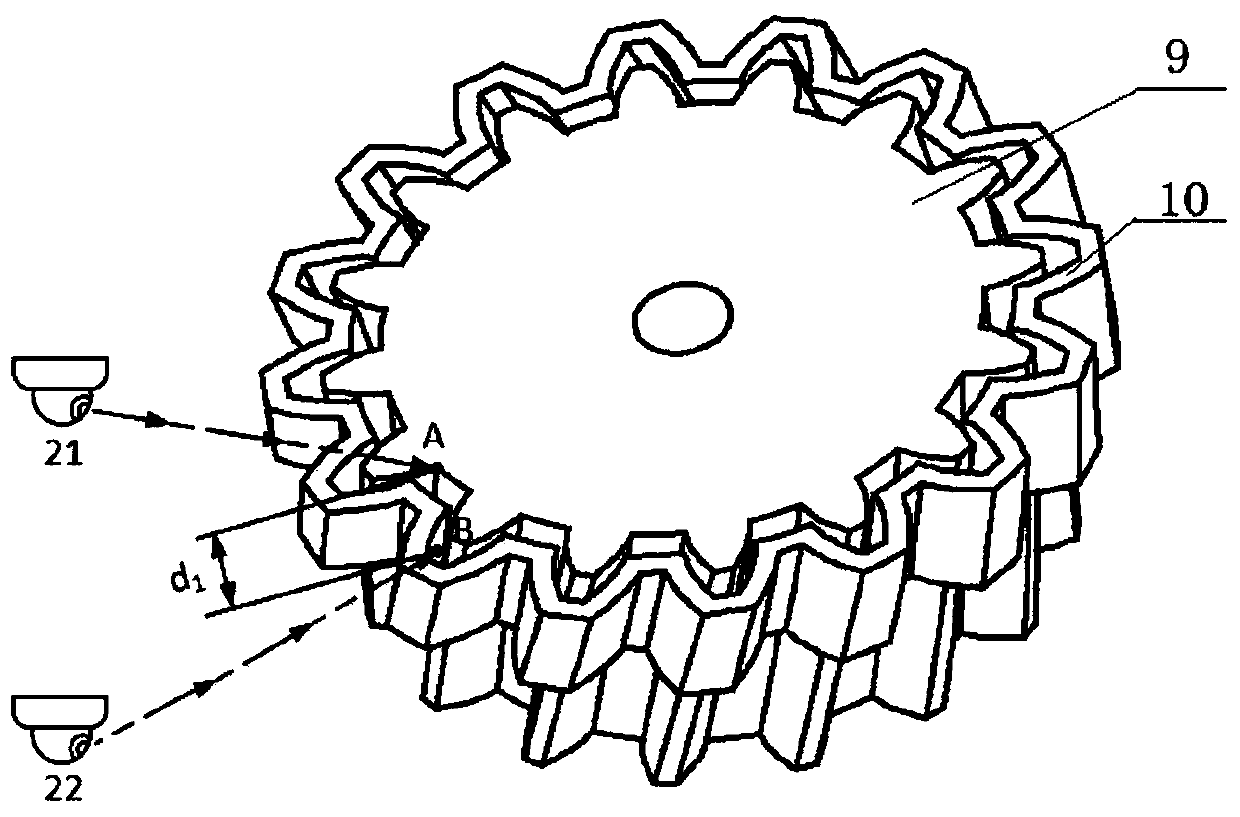
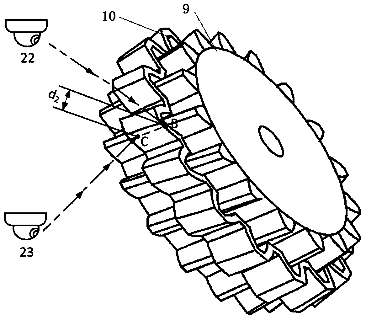
The invention relates to a layer-by-layer heating device for cylindrical bevel gears. The device comprises a heating device, a rotating platform device, a worktable, a lifting device, a vertical powersupply table, a base and multiple infrared temperature measuring cameras; the heating device comprises a profiling induction coil and an induction coil bracket; one end of the induction coil bracketis vertically fixed on the vertical power supply table; the profiling induction coil is fixed at the other end of the induction coil bracket; the profiling induction coil is positioned above the rotating platform device; the rotating platform device is used for fixedly supporting the cylindrical bevel gears; the rotating platform device is mounted on the worktable; the worktable is mounted on thelifting device; the lifting device is fixed on the base; and the vertical power supply table is vertically fixed on the base. The invention further provides a layer-by-layer heating method for the cylindrical bevel gears; the influence caused by the end surface effect is effectively reduced; the depth uniformity of tooth surface hardening layers is improved; and the service life of the cylindricalbevel gears is prolonged.

Description

Technical field [0001] The invention belongs to the technical field of heat treatment, and particularly relates to a layer-by-layer heating device and a method for cylindrical helical gears. Background technique [0002] Induction quenching is one of the important processes of heat treatment. It uses induction current to quench the surface of the workpiece. After heating and cooling, the surface obtains a martensitic structure with high hardness, while the internal structure still has good toughness, plasticity and high Strength, etc., to meet the needs of parts with high service life under alternating loads. Induction hardening is especially popular because of its high production efficiency, low energy consumption, low pollution and easy automation. In the strengthening method of gears, it forms four basic processes together with quenching and tempering, carburizing and nitriding. With the development of industrial technology, the parameters of various mechanical equipment have...

Claims


Application Information

Patent Timeline
Patent Type & Authority Applications(China)
IPC IPC(8): C21D9/32C21D1/10C21D1/62
CPCY02P10/25
Inventor 李大龙张天雄
Owner TAICANG FANSHENG ELECTRONICS TECH CO LTD
Why Eureka
Eureka Blog
Learn More