
Water seepage drainage structure outside side wall of foundation pit and construction method thereof

A foundation pit and dredging technology, which is applied in basic structure engineering, excavation, construction, etc., can solve the problems of the impact of underground structure construction, the small amount of water collected by pipe wells, and the poor permeability of weakly permeable layers, etc., and achieves fast construction speed and flexible layout. , the effect of simple construction process

Pending Publication Date: 2019-05-31
甘肃中建市政工程勘察设计研究院有限公司
View PDF9 Cites 1 Cited by
  • Summary
  • Abstract
  • Description
  • Claims
  • Application Information

AI Technical Summary

Problems solved by technology

This dewatering method has been widely used in foundation pits with shallow groundwater levels and thick aquitards. The permeability is poor or the seepage of groundwater is slow, and the water catchment in the tube well is small, resulting in a high water level line of the tube well dewatering funnel, and the precipitation effect is not ideal, and the groundwater in the blind area of ​​the tube well dewatering funnel and the upper part of the aquifer cannot be drained through the tube well, and the foundation pit is excavated During the process, it will flow into the foundation pit along the side wall of the foundation pit, seriously affecting the stability of the soil mass on the side wall of the foundation pit and the construction progress in the foundation pit
[0003] At present, for this kind of situation, it is generally used to collect water in the pit or use light well points for dewatering. However, for foundation pit projects with complex stratum structures, the bedrock surface changes greatly, and bedrock seepage cannot be determined when light well points are arranged. The problem is that the treatment effect is not complete, and the use of drainage in the pit will have a certain impact on the earthwork excavation and the construction of the underground structure in the later stage, and it will also have a certain impact on the civilized construction of the project.

Method used


Image

  • Water seepage drainage structure outside side wall of foundation pit and construction method thereof
  • Water seepage drainage structure outside side wall of foundation pit and construction method thereof
  • Water seepage drainage structure outside side wall of foundation pit and construction method thereof

Examples


Embodiment Construction

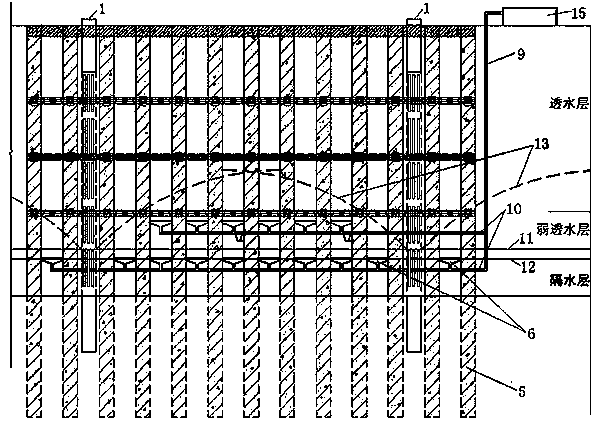
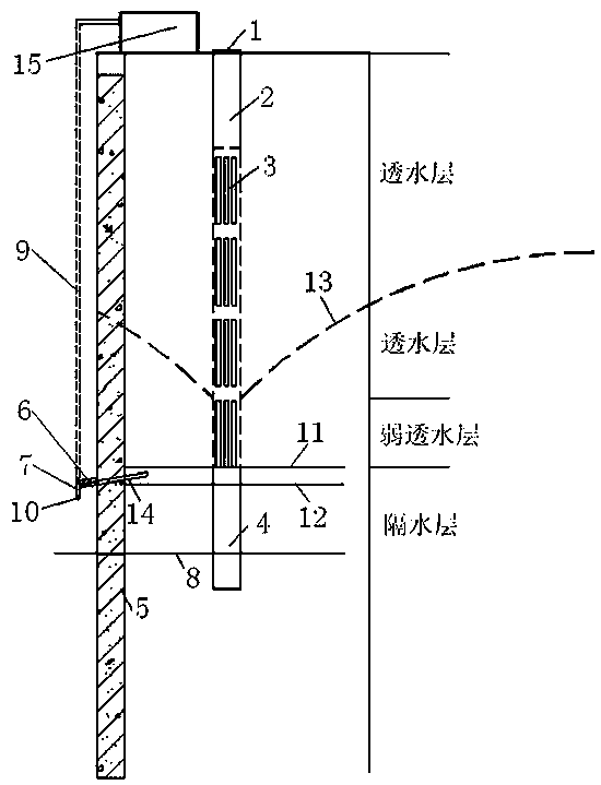
[0029] refer to Figure 1~Figure 5 , the embodiment of the present invention provides a drainage structure for external seepage on the side wall of the foundation pit, which mainly includes a plurality of water diversion components arranged on the side wall of the foundation pit along the horizontal direction, and a water diversion component arranged below and connected to it Horizontal confluence pipe 10, the vertical drainage pipe 9 that communicates with the horizontal confluence pipe 10 and extends to the top of the foundation pit, and the drainage pump 15 that is connected to the vertical drainage pipe 9 on the ground at the top of the foundation pit; the water diversion assembly is located on the side of the foundation pit A certain distance (for example, 20~30cm) below the seepage point on the wall, the position is fixed by the part embedded in the side wall of the foundation pit, and the seepage water is collected and introduced into the horizontal manifold 10 by the pa...


PUM


Abstract

The invention relates to a water seepage drainage structure outside a side wall of a foundation pit and a construction method thereof. The structure comprises a plurality of water diversion assembliesarranged on the side wall of the foundation pit in the horizontal direction, a horizontal confluence pipe arranged below the water diversion assemblies and communicated with the water diversion assemblies, a vertical drainage pipe communicated with the horizontal confluence pipe and extending towards the top of the foundation pit, and a drainage pump arranged on the ground of the top of the foundation pit and connected with the vertical drainage pipe. The water diversion assemblies are located at a distance below the water seepage point on the side wall of the foundation pit. The position isfixed by the portion embedded in the side wall of the foundation pit, and the external water seepage is collected and introduced into the horizontal confluence pipe through the portion exposed on theside wall of the foundation pit. The application of the water seepage drainage structure can prevent the underground water from soaking the side wall of the foundation pit and prevent the undergroundwater from collecting into the foundation pit to influence the bearing capacity of the foundation pit and the construction progress. In addition, the drainage structure is simple in construction process and fast in construction speed, and can be flexibly arranged according to the seepage amount and the position of the seepage point in the excavation process of the side wall of the foundation pit.

Description

technical field [0001] The invention relates to the technical field of foundation pit excavation groundwater control, in particular to a foundation pit side wall external seepage drainage structure and a construction method thereof. Background technique [0002] At present, in the process of dewatering foundation pit tube wells, dewatering wells at a certain distance are generally arranged along the periphery of the foundation pit, and the groundwater in the foundation pit is reduced by pumping water through tube wells during the earthwork excavation process, which is convenient for earthwork excavation and underground structure construction. This dewatering method has been widely used in foundation pits with shallow groundwater levels and thick aquitards. The permeability is poor or the seepage of groundwater is slow, and the water catchment in the tube well is small, resulting in a high water level line of the tube well dewatering funnel, and the precipitation effect is no...

Claims


Application Information

Patent Timeline
Patent Type & Authority Applications(China)
IPC IPC(8): E02D17/02E02D19/10
Inventor 何腊平闫文进曹程明项龙江龙照孔维刚
Owner 甘肃中建市政工程勘察设计研究院有限公司
Learn More