Parallel data acquisition circuit and an automatic acquisition method for a plurality of rotary transformers

A technology of data acquisition circuit and rotary transformer, which is applied in the direction of analog-to-digital converter, electrical digital data processing, input/output process of data processing, etc. It can solve the problems of slow data transmission speed of circuits and methods, and achieve modularization of circuit structure Effect

Active Publication Date: 2019-05-31
HARBIN INST OF TECH
View PDF7 Cites 1 Cited by
  • Summary
  • Abstract
  • Description
  • Claims
  • Application Information

AI Technical Summary

Problems solved by technology

[0004] The purpose of the present invention is to provide a parallel data acquisition circuit and automatic acquisition method for multiple rotary transformers, so as to solve the problem of slow data transmission speed in the circuit and mode of serial data output for simultaneously collecting data output of multiple rotary transformers

Method used


Image

  • Parallel data acquisition circuit and an automatic acquisition method for a plurality of rotary transformers
  • Parallel data acquisition circuit and an automatic acquisition method for a plurality of rotary transformers
  • Parallel data acquisition circuit and an automatic acquisition method for a plurality of rotary transformers

Examples


specific Embodiment approach 1

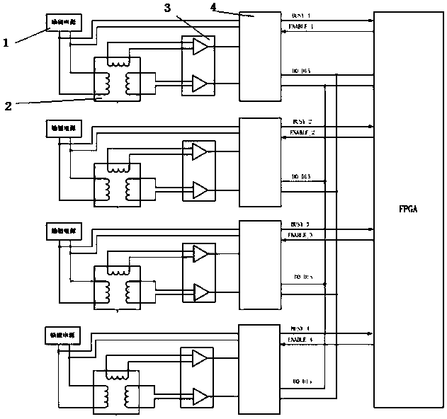
[0015] Specific implementation mode one: combine figure 1 Describe this embodiment, the parallel data acquisition circuit of this embodiment comprises four excitation power supplies 1, four rotary transformers 2, four differential filter circuits 3, four AD2S80A chips 4 and a field programmable gate array FPGA;

[0016] Excitation power supply 1: each excitation power supply 1 is connected to an excitation winding of a rotary transformer 2 to provide excitation current, and each excitation power supply 1 is connected to an AD2S80A chip 4 to provide it with working power;

[0017] Resolver 2: each resolver 2 includes an excitation winding, an iron core and two induction windings;

[0018] Differential filter circuit 3: the two input terminals of the sinusoidal differential signal of each differential filter circuit 3 are connected to both ends of an induction winding of the rotary transformer 2, and the input signal is differentially calculated and filtered and output; each dif...

specific Embodiment approach 2

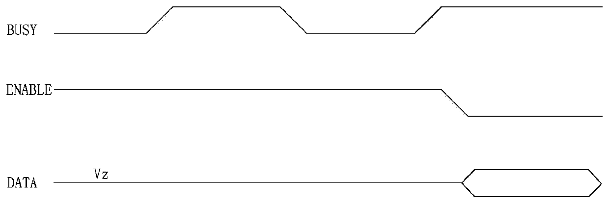
[0023] Specific implementation mode two: combination figure 2This embodiment will be described. This embodiment is further limited to the embodiment as follows: AD2S80A’s analog / digital conversion data output is indicated by the BUSY signal. When the BUSY signal is at a high level, it means that the AD2S80A is converting the angle information of the resolver. When the BUSY signal is at a low level, Indicates that the conversion is complete and the data can be read; the ENABLE signal of the FPGA controls the output of the parallel conversion data. When the ENABLE signal is high, the parallel data bus is in a high-impedance state; when the ENABLE signal is low, the parallel data bus is valid. Therefore, through the BUSY signal indication of the four modules, the working status of the modules can be confirmed, and the data output of each module can be realized by controlling the ENABLE signal.

specific Embodiment approach 3

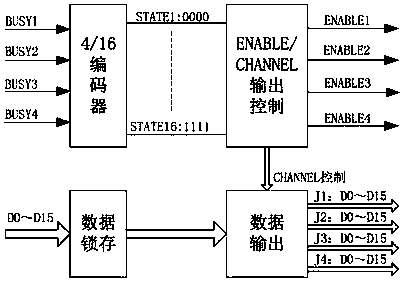
[0024] Specific implementation mode three: combination image 3 This embodiment will be described. Compared with the embodiment, this embodiment is further limited in that: the collection and processing module of this embodiment is implemented based on FPGA. FPGA has parallel data processing function, which can realize parallel data processing with four modules AD2S80A, and meet the requirements of fast and real-time data. In order to prevent false triggering caused by signal interference, a digital filter is added to each BUSY signal, and then the BUSY signals output by the 4 modules are encoded, and there are 16 states in total. In order to prevent parallel data bus conflicts, it is necessary to control each data read in the FPGA program, and only the ENABLE signal of one module channel is valid. In order to realize the automatic collection of data, according to the 16 states encoded by the BUSY signal, the ENABLE signal is targetedly controlled. When one channel is valid, ...


PUM


Abstract

The invention discloses a parallel data acquisition circuit and an automatic acquisition method for a plurality of rotary transformers, and relates to an acquisition circuit for data output of a plurality of rotary transformers and an automatic acquisition method for data output. The problem that data transmission speed is low when serial data output is adopted for simultaneously collecting data output of a plurality of rotary transformers is solved. Wherein the acquisition circuit comprises a plurality of excitation power supplies, a plurality of rotary transformers, a plurality of differential filter circuits, a plurality of AD2S80A chips and a field programmable gate array; 16-bit parallel output data of the AD2S80A is hung on the same data bus; The circuit is connected to an IO pin ofa field programmable logic device FPGA. Through automatic acquisition and switching of BUSY and ENABLE signals related to each AD2S80A, multiple 16-bit parallel data information acquisition of independent rotary transformers is realized, and the method is widely applied to the field of multi-axis sensor systems integrated with robot driving and control and multi-channel parallel data conversion needing to be rapidly acquired.

Description

technical field [0001] The invention relates to a collection circuit for data output of multiple rotary transformers, and also relates to an automatic collection method for data output of multiple rotary transformers. Background technique [0002] The driving and control performance of the robot determines the operation and control performance of the robot. With the constraints on the power consumption, volume and cost of the robot system, the multi-axis driving and control integration technology of the robot has become an important direction for the development of robots. The data output of multiple resolvers can provide absolute angle information and speed information for joint motors and realize vector control of the motors. It is the core unit for realizing a resolver-based robot multi-axis servo control system. In addition, the absolute position information of the motor end is helpful for the robot to realize position control, compliance control and force control in Car...

Claims


Application Information

Patent Timeline
Patent Type & Authority Applications(China)
IPC IPC(8): G06F3/05H03M1/12
Inventor 倪风雷郭闯强金明河刘宏
Owner HARBIN INST OF TECH
Why Eureka
Try Eureka