Three-pole type magnetic coupling mechanism transmitting terminal and magnetic coupling mechanism applied to wireless power supply system of electric automobile

A wireless power supply, electric vehicle technology, applied in electric vehicle charging technology, electric vehicles, circuits, etc., can solve the problems of poor electromagnetic compatibility, serious magnetic leakage radiation, etc., to reduce electromagnetic radiation, weaken magnetic field leakage, and high output power Effect

Inactive Publication Date: 2019-06-07
HARBIN INST OF TECH
View PDF6 Cites 4 Cited by
  • Summary
  • Abstract
  • Description
  • Claims
  • Application Information

AI Technical Summary

Problems solved by technology

[0004] The purpose of the present invention is to solve the problem of poor electromagnetic compatibility and serious magnetic flux leakage radiation in the transmitting end of the magnetic coupling mechanism currently used

Method used


Image

  • Three-pole type magnetic coupling mechanism transmitting terminal and magnetic coupling mechanism applied to wireless power supply system of electric automobile
  • Three-pole type magnetic coupling mechanism transmitting terminal and magnetic coupling mechanism applied to wireless power supply system of electric automobile
  • Three-pole type magnetic coupling mechanism transmitting terminal and magnetic coupling mechanism applied to wireless power supply system of electric automobile

Examples


Embodiment Construction

[0021] The technical solutions in the embodiments of the present invention will be clearly and completely described below in conjunction with the accompanying drawings in the embodiments of the present invention. Obviously, the described embodiments are only some of the embodiments of the present invention, not all of them. Based on the embodiments of the present invention, all other embodiments obtained by persons of ordinary skill in the art without making creative efforts belong to the protection scope of the present invention.

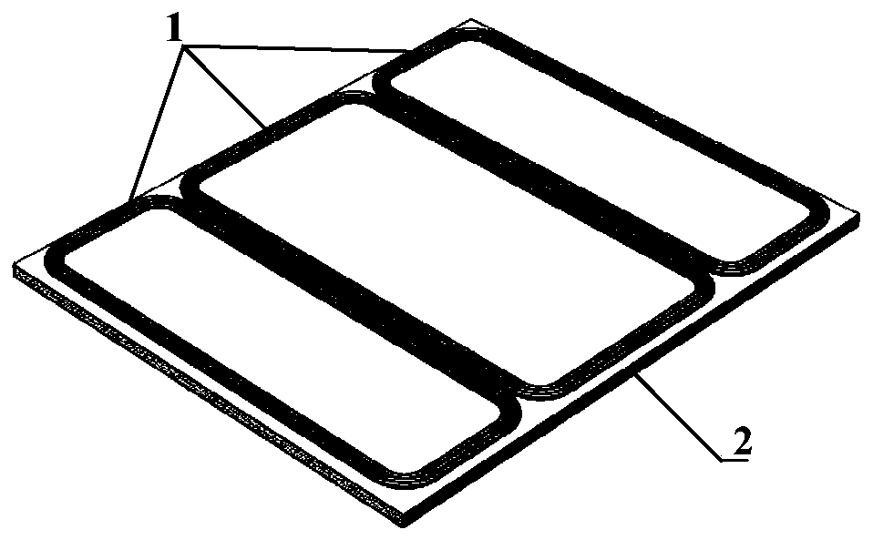
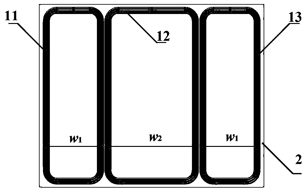
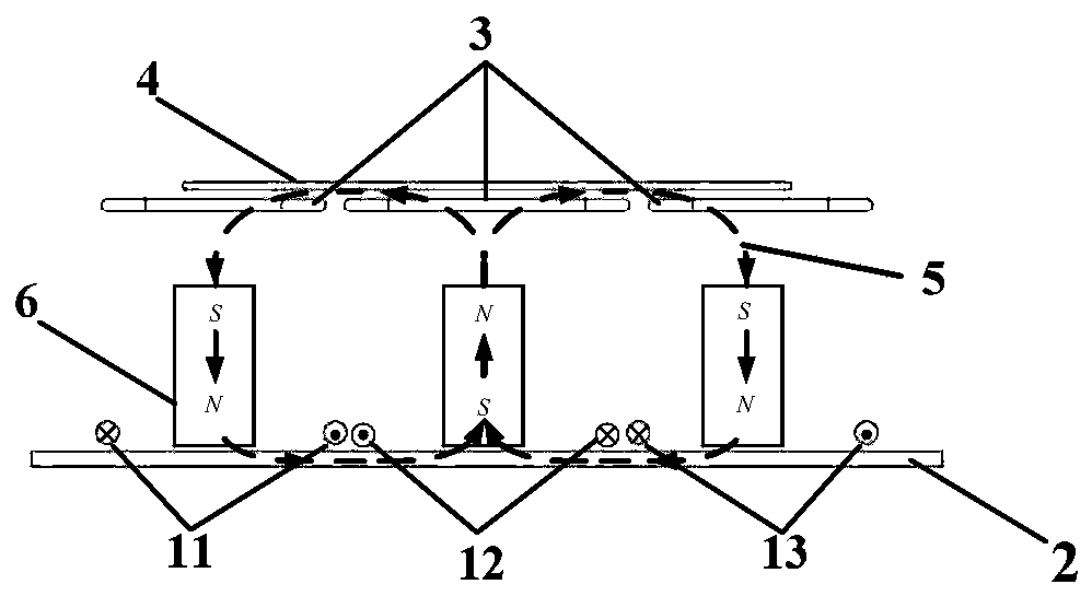
[0022] combine figure 1 and figure 2 , the present invention proposes a transmitting end of a three-pole magnetic coupling mechanism applied to a wireless power supply system of an electric vehicle. The transmitting end is composed of two parts, one is a transmitting coil 1 for exciting a magnetic field and transmitting electric energy in space, and the other is a One part is the transmitting end magnetic core 2 for constraining the direction of ...


PUM


Abstract

The invention provides a three-pole type magnetic coupling mechanism transmitting terminal and magnetic coupling mechanism applied to a wireless power supply system of an electric automobile. The three-pole type magnetic coupling mechanism transmitting terminal consists of two parts, one part is a transmitting coil and the other part is a transmitting terminal magnetic core; the transmitting terminal magnetic core is laid below the transmitting coil; and the transmitting coil consists of three rectangular coils connected in series, the width of the left-side rectangular coil is w1, the width of the middle rectangular coil is w2, the width of the right-side rectangular coil is w1, the lengths of the three rectangular coils are the same, and the three rectangular coils are parallelly placedon the same horizontal plane. According to the structures of the three-pole type magnetic coupling mechanism transmitting terminal and magnetic coupling mechanism applied to the wireless power supplysystem of the electric automobile, the directions of magnetic fields generated by the transmitting coil in a receiving coil are the same and the magnetic fields are overlapped mutually, and the transmission power of the system is increased; while the directions of magnetic fields generated outside the transmitting coil by the transmitting coil are in the opposite directions, and a leakage magneticfield is weakened; and the electromagnetic radiation generated by the magnetic coupling mechanism is reduced, so that the wireless power supply system cannot cause radiation hazards to electronic equipment and pedestrians around automobiles, and the problem of poor electromagnetic compatibility of an existing magnetic coupling mechanism is solved.

Description

technical field [0001] The invention belongs to the technical field of wireless power transmission, and in particular relates to a transmitting end of a three-pole magnetic coupling mechanism applied to a wireless power supply system of an electric vehicle and a magnetic coupling mechanism thereof. Background technique [0002] As a representative of new energy vehicles, electric vehicles have become the mainstream solution to effectively alleviate environmental pollution and solve the energy crisis all over the world by virtue of their obvious advantages of low energy consumption and low exhaust emissions. However, there are many problems in the traditional contact charging method: (1) Frequent maintenance is required: there is mechanical friction and contact loss between the charging pile and the charging receiving head of the electric vehicle; (2) Poor safety: both the power supply interface and the charging plug have high voltage , will pose a safety threat to the operat...

Claims


Application Information

Patent Timeline
IPC IPC(8): H02J50/10H02J50/70H01F38/14B60L53/12
CPCY02T10/70Y02T10/7072Y02T90/14
Inventor 董帅宋贝贝朱春波高鑫崔淑梅
Owner HARBIN INST OF TECH
Why Eureka
Try Eureka