
A Rotating Magnetic Field Positioning Method Based on Trigonometric Function Fitting

A technology of rotating magnetic field and trigonometric function, which is applied in the field of navigation and positioning, can solve the problems of the introduction of uncharacteristic vector method positioning method, the dependence of magnetic induction intensity data, and the weak anti-interference ability of the algorithm, so as to achieve good positioning accuracy and stability, and easy to noise , Strong anti-interference ability

Active Publication Date: 2021-04-02
HARBIN INST OF TECH
View PDF5 Cites 0 Cited by
  • Summary
  • Abstract
  • Description
  • Claims
  • Application Information

AI Technical Summary

Problems solved by technology

The disadvantage of the magnetic field strength method is that it relies too much on the magnetic induction data measured by the sensor, resulting in weak anti-interference ability of the algorithm, so it is not suitable for areas with more complex electromagnetic fields.
The disadvantage of the gradient tensor method is that in order to measure the magnetic gradient tensor, at least eight three-axis fluxgate sensors need to be formed into a measurement array, so the requirements for the measurement device are relatively high
[0005] At present, there is no introduction to the positioning method of the eigenvector method.

Method used


Image

  • A Rotating Magnetic Field Positioning Method Based on Trigonometric Function Fitting
  • A Rotating Magnetic Field Positioning Method Based on Trigonometric Function Fitting
  • A Rotating Magnetic Field Positioning Method Based on Trigonometric Function Fitting

Examples


Embodiment 1

[0079] This embodiment provides a rotating magnetic field positioning method based on trigonometric function fitting, no obstacles are arranged between the magnetic beacon and the target, and the positioning results achieved by the rotating magnetic field positioning method based on trigonometric function fitting according to the present invention are compared with The positioning results achieved by the magnetic field strength positioning method are compared. A sinusoidal current with a frequency of 20Hz and an amplitude of 4A is passed into the magnetic beacon, and the initial position of the magnetic beacon in the entire coordinate system (p x ,p y ,p z )=(0,0,0), the target positions are (4,4,4), (5,5,5), (6,6,6) respectively. Sampling at a sampling frequency of 1000 Hz from the magnetometer installed on the target to be positioned, and performing calculations according to the steps of the above method, the positioning results can be obtained as shown in Table 1 below. I...

Embodiment 2

[0083] The difference between this embodiment and the above-mentioned embodiment is that an obstacle with an attenuation coefficient of 0.9 is arranged between the magnetic beacon and the target, and the positioning result achieved by the rotating magnetic field positioning method based on trigonometric function fitting according to the present invention is compared with that according to the magnetic field The localization results achieved by the intensity localization method are compared. A sinusoidal current with a frequency of 20Hz and an amplitude of 4A is passed into the magnetic beacon, and the initial position of the magnetic beacon in the entire coordinate system (p x ,p y ,p z )=(0,0,0), the target positions are (4,4,4), (5,5,5), (6,6,6) respectively. Sampling at a sampling frequency of 1000 Hz from the magnetometer installed on the target to be positioned, and performing calculations according to the steps of the above method, the positioning results can be obtain...

Embodiment 3

[0087] The difference between this embodiment and the above-mentioned embodiment is that an obstacle with an attenuation coefficient of 0.95 is arranged between the magnetic beacon and the target, and the positioning result achieved by the rotating magnetic field positioning method based on trigonometric function fitting according to the present invention is compared with that according to the magnetic field The localization results achieved by the intensity localization method are compared. A sinusoidal current with a frequency of 20Hz and an amplitude of 4A is passed into the magnetic beacon, and the initial position of the magnetic beacon in the entire coordinate system (p x ,p y ,p z )=(0,0,0), the target positions are (4,4,4), (5,5,5), (6,6,6) respectively. Sampling at a sampling frequency of 1000 Hz from the magnetometer installed on the target to be located, and performing calculations according to the steps of the above method, the positioning results can be obtained...


PUM


Abstract

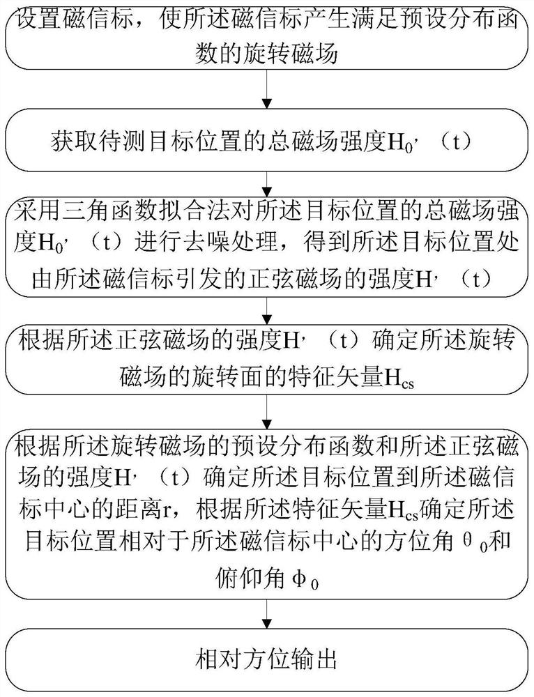
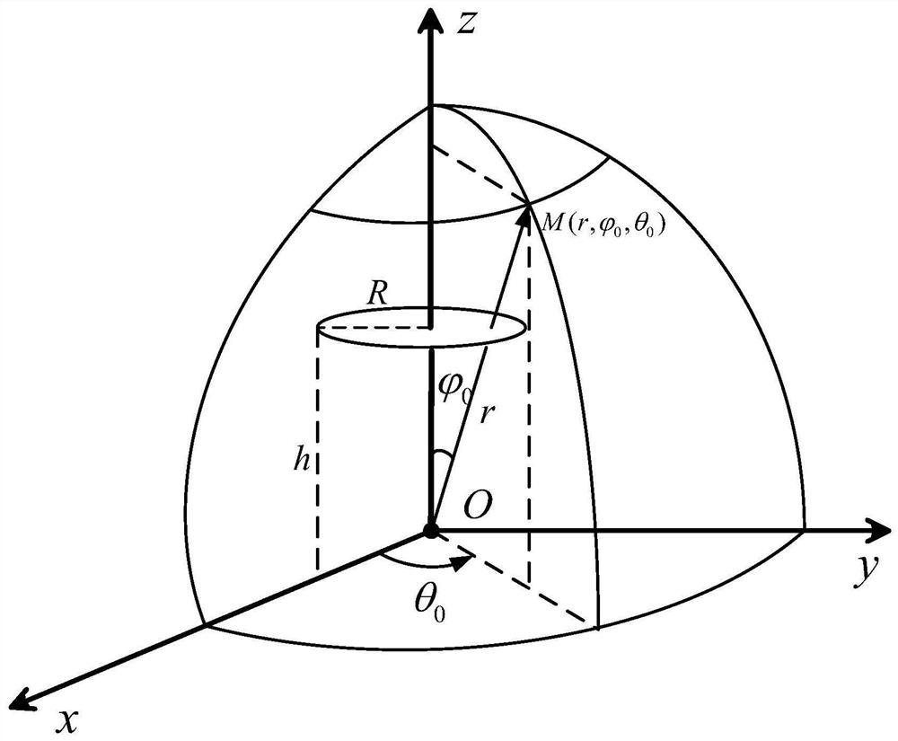
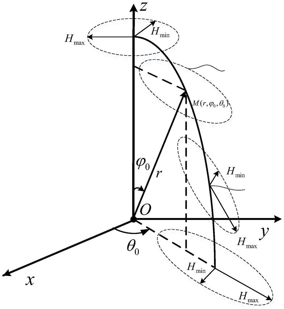
The invention provides a rotating magnetic field positioning method based on trigonometric function fitting, and relates to the technical field of navigation and positioning. The rotating magnetic field positioning method based on the trigonometric function fitting comprises the steps that a magnetic beacon is set, and the magnetic beacon generates a rotating magnetic field meeting a preset distribution function; the total magnetic field intensity H<0>'(t) of a to-be-measured target position is obtained; a trigonometric function fitting method is adopted to obtain the intensity H'(t) of a sinusoidal magnetic field; a characteristic vector H<cs> of a rotating surface of the rotating magnetic field is determined according to the intensity H'(t) of the sinusoidal magnetic field; and a distance r from the target position to the center of the magnetic beacon is determined according to the preset distribution function and the intensity H'(t) of the sinusoidal magnetic field, and an azimuth angle theta<0> and a pitch angle phi<0> of the target position are determined according to the characteristic vector H<cs>. According to the rotating magnetic field positioning method based on the trigonometric function fitting, the antijamming capability is high, the positioning errors are not accumulated with time, and the accurate positioning service can be provided.

Description

technical field [0001] The invention relates to the technical field of navigation and positioning, in particular to a rotating magnetic field positioning method based on trigonometric function fitting. Background technique [0002] Navigation and positioning technology is a multidisciplinary engineering application technology. It has broad application prospects in military and civilian fields. In recent years, navigation and positioning services have become an indispensable part of people's daily life and work. It has made a huge contribution to economic development. [0003] In the prior art, the positioning accuracy in outdoor environments can basically meet the needs of daily life. However, in environments such as underground, indoors, and factories, the accuracy of satellite navigation and positioning is relatively low due to changing terrain and various interferences. Low, or even unable to complete the positioning. Indoor navigation and positioning methods are mainly...

Claims


Application Information

Patent Timeline
Patent Type & Authority Patents(China)
IPC IPC(8): G01C21/08
Inventor 李清华王煜解伟男奚伯齐郑元勋胡捷凯
Owner HARBIN INST OF TECH
Learn More