
Multistable energy capture device with linkage effect

An energy capture, multi-stable technology, applied in piezoelectric effect/electrostrictive or magnetostrictive motors, generators/motors, electrical components, etc., can solve the difficulties of wire layout, battery power supply needs to be replaced regularly, multiple There are few researches on the degree of freedom energy harvester, etc., to achieve the effects of high overall energy conversion efficiency, improved utilization feasibility, and good applicability

Inactive Publication Date: 2019-06-14
NORTHWESTERN POLYTECHNICAL UNIV
View PDF5 Cites 8 Cited by
  • Summary
  • Abstract
  • Description
  • Claims
  • Application Information

AI Technical Summary

Problems solved by technology

However, the following problems are faced: limited space or environmental influence in a specific environment, difficulty in wire layout for wired power supply, and regular replacement of batteries for power supply, etc.
[0006] The above studies mainly focus on the multi-stable effects of single-degree-of-freedom systems, but there are few studies on multi-degree-of-freedom energy harvesters for linkage effects

Method used


Image

  • Multistable energy capture device with linkage effect
  • Multistable energy capture device with linkage effect
  • Multistable energy capture device with linkage effect

Examples


Embodiment 1

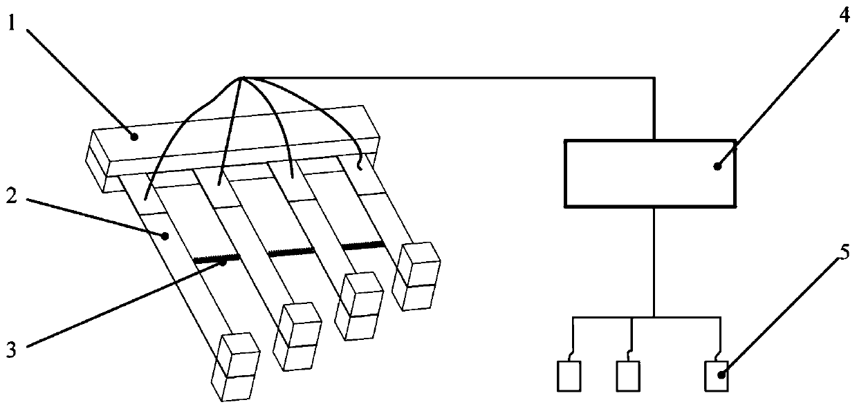
[0032] Such as figure 1 As shown, a schematic diagram of the working principle of a multi-stable energy harvesting device with linkage effect in the present invention. The multi-stable energy harvesting device includes: an energy harvesting device base 1 , a spring 2 , an energy harvester 3 , and an electric energy storage and management system 4 . The inventive device converts the vibration energy in the environment into electrical energy through the positive piezoelectric effect, passes through the electrical energy storage and management system 4, and then supplies energy to the sensor 5 to realize real-time health monitoring of the environment or structure.

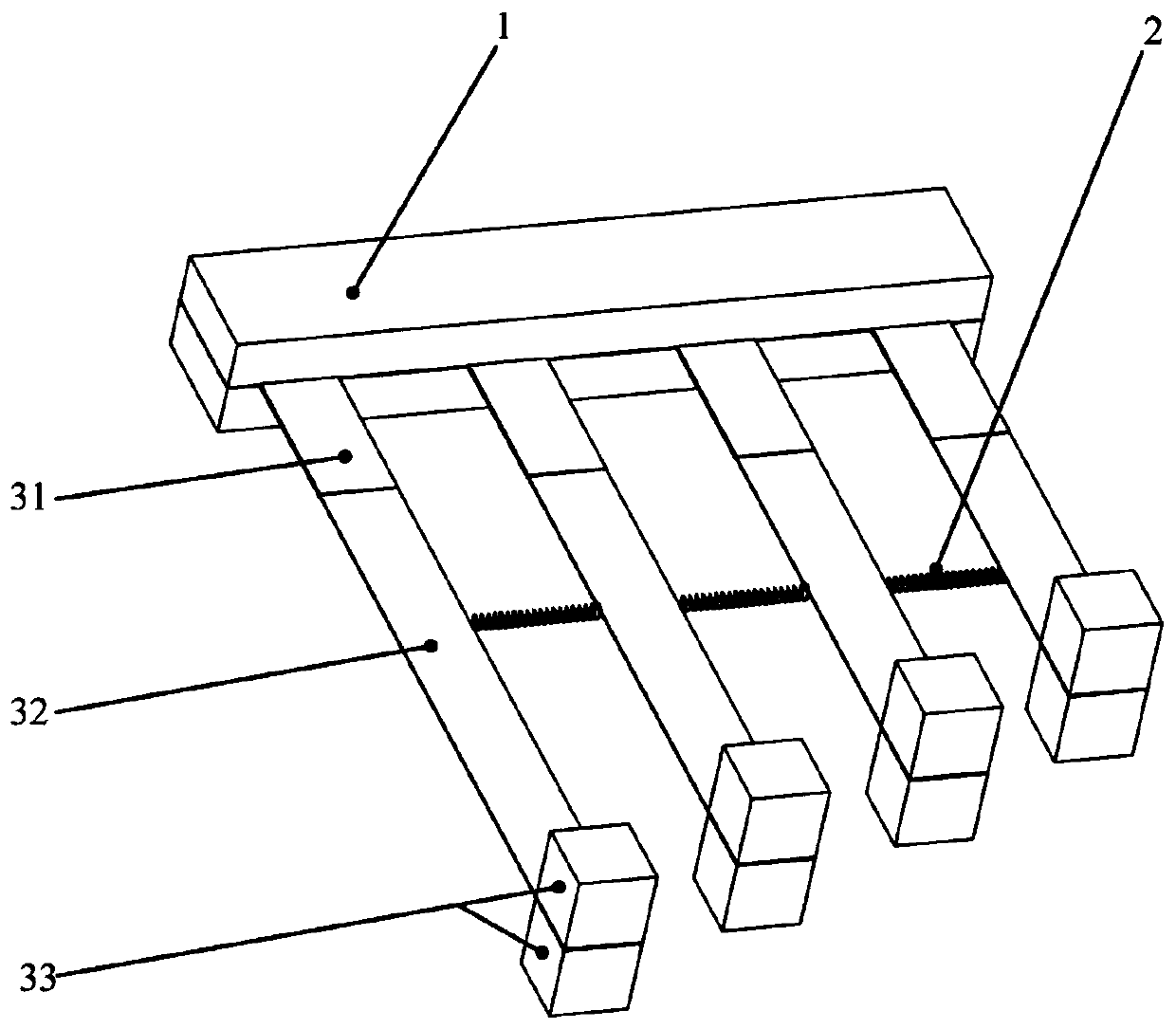
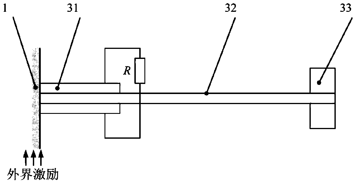
[0033] Such as figure 2 A schematic diagram of the overall three-dimensional structure of the device is shown in . Each energy harvester 3 is connected by a spring 2 and then arranged in a row on the base 1 of the energy harvesting device. Energy harvester 3 is mainly made of piezoelectric sheet 31, cantilever bea...

Embodiment 2

[0039] The present invention is a multi-stable energy capture device with linkage effect, and the specific implementation is as follows:

[0040] Paste the piezoelectric sheet 31 on the cantilever beam 32, the piezoelectric sheet is connected in series, then fix the permanent magnet 33 at the free end of the cantilever beam 32, and fix the spring 2 on the cantilever beam. The rest of the arrays of energy harvesters 3 are manufactured in the same way, and finally fixed on the base 1 of the energy harvesting device.

[0041] Connect the recovered electrical energy of the energy harvesters 3 of all arrays to the electrical energy storage and management system 4 . The entire inventive device is installed in a vibrating environment to power wireless sensors for environmental or structural health monitoring.

[0042] The device of the present invention connects different energy harvesters 3 through springs 2, and then arrays them on the base 1 of the energy harvesting device to for...


PUM


Abstract

The invention discloses a multistable energy capture device with a linkage effect. The device comprises an energy capture device foundation bed, springs, an array energy capture device and an electricenergy storage and management system. An integral working principle is disclosed in a diagram 1, external vibrational excitation enables a piezoelectric cantilever beam to generate deformation, a direct piezoelectric effect is used, a piezoelectric plate converts vibration energy into electric energy, and then, the electric energy is conveyed to an electric energy storage and management system torealize a self-energy-supply sensor. The multistable energy capture device with the linkage effect has the following advantages that: (1) an array layout with different energy capture devices is adopted, each energy capture device has different inherent frequencies, and energy can be efficiently recovered in a large frequency range; and (2) the springs are adopted to connect the array energy capture devices, in addition, consistent acting force among magnets on an end part realizes the energy capture device linkage effect of the array, the whole device presents a multistable effect, and energy capture efficiency is improved. In addition, compared with a traditional multistable energy capture device based on an external magnet magnetic coupling effect, the device disclosed by the inventionhas a simple structural layout, miniaturization even microminiaturization can be realized, and electric energy is provided for the self-energy-supply sensor of the future Internet of Things era.

Description

technical field [0001] The invention is a multi-stable energy capture device with linkage effect, which mainly converts the vibration energy existing in the environment into electric energy, and then supplies energy to wireless sensors to realize self-powered sensors for environmental or structural health monitoring. Background technique [0002] With the development of microelectronic devices, low-power sensor technology has made great progress, and will develop in the direction of low power consumption and miniaturization in the future, laying the foundation for the rapid development of the Internet of Things. At present, sensors are mainly used for real-time health monitoring of the environment or structure, and realize data collection and transmission of sensor nodes. [0003] At present, the energy supply methods of sensors mainly include: wired power supply and battery power supply. However, the following problems are faced: limited space or environmental influence in...

Claims


Application Information

Patent Timeline
Patent Type & Authority Applications(China)
IPC IPC(8): H02N2/18
Inventor 梅旭涛周生喜
Owner NORTHWESTERN POLYTECHNICAL UNIV
Learn More