Novel scalp dilator for skull defect repair surgery

A spreader and repair technique, applied in the field of new scalp spreader, can solve the time-consuming and labor-intensive problems, and achieve the effect of improving safety, avoiding accidental brain tissue injury, and speeding up the operation

Pending Publication Date: 2019-06-18
BEIJING NEUROSURGICAL INST
View PDF12 Cites 2 Cited by
  • Summary
  • Abstract
  • Description
  • Claims
  • Application Information

AI Technical Summary

Problems solved by technology

Since there is currently no suitable surgical instrument to help lift the scalp and locate the bone margin, the above set of actions (touching with the left hand, locating the bone margin—recording the position of the bone margin—changing the tweezers with the left hand—lifting the scalp—holding it with the right hand Separating the subcutaneous tissue with a knife—cutting the fibrous granulation layer outside 1cm to expose the bone margin) needs to be done carefully and repeatedly until the surface of the skull around the defect is fully exposed, which is time-consuming and laborious

Method used


Image

  • Novel scalp dilator for skull defect repair surgery
  • Novel scalp dilator for skull defect repair surgery
  • Novel scalp dilator for skull defect repair surgery

Examples


no. 1 example

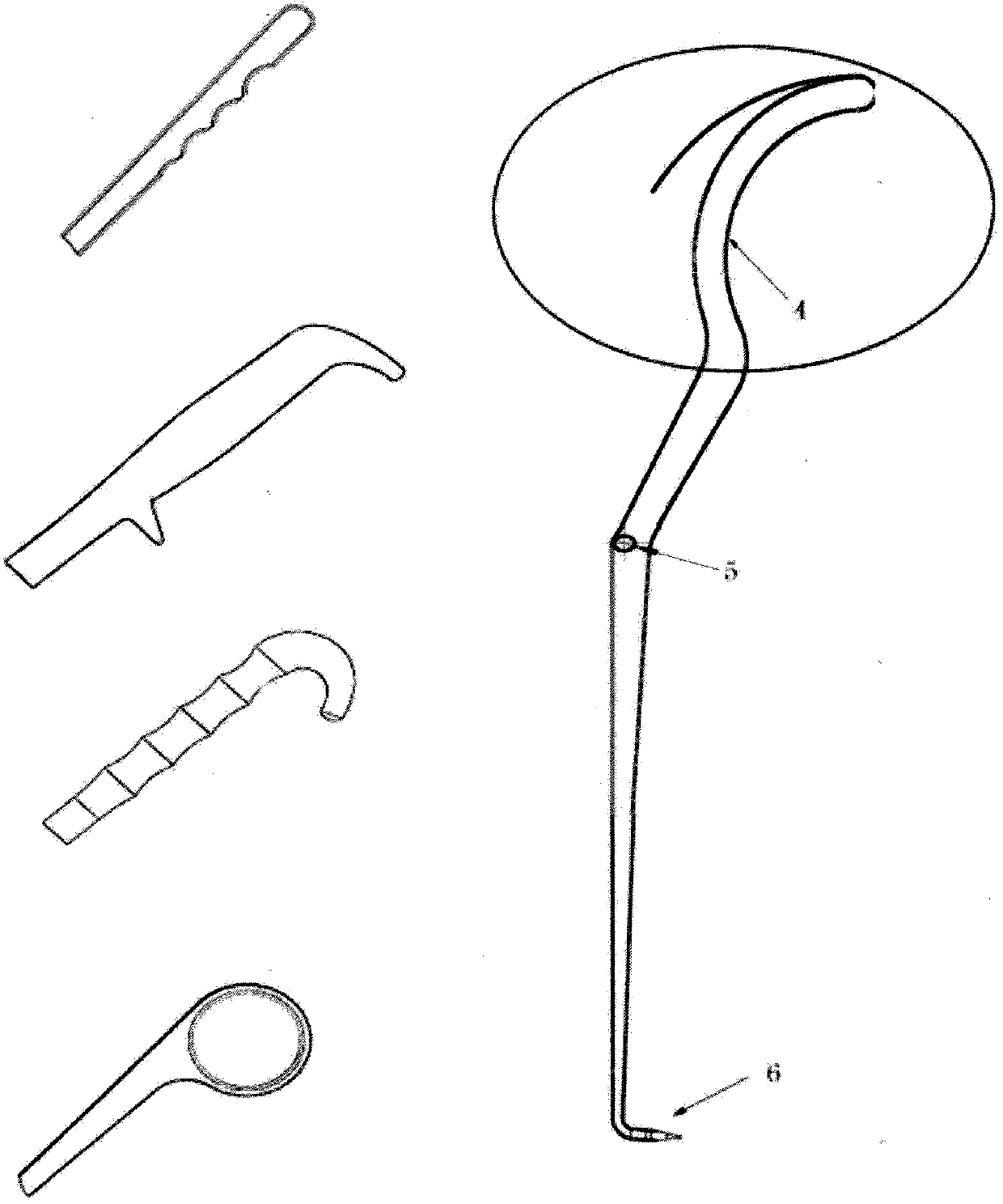
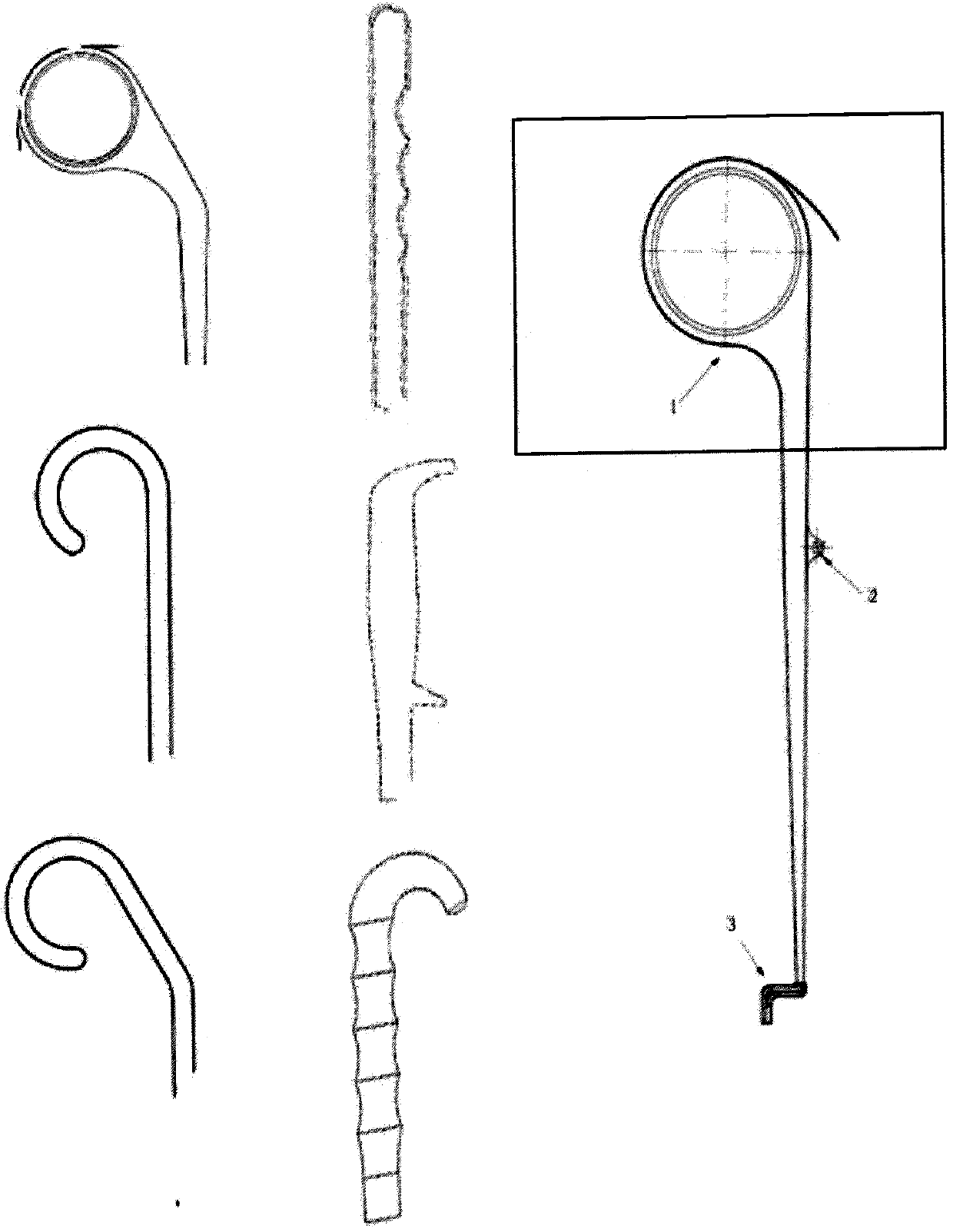
[0030] Such as Figure 1-3 As shown, the special scalp spreader for skull defect repair surgery of the present invention is composed of a first rod and a second rod. The two parts of the first rod and the second rod are respectively divided into five parts from top to bottom, the top, the upper part, the middle part, the lower part and the foot part. The top of the first rod is designed as a ring-shaped or cylindrical handle, which is convenient for fingers to be inserted into or directly held by a hand for firm holding. The upper part and the lower part of the first rod are vertical rods. The middle part of the first rod is provided with a shaft hole 2 embedded with a screw, which is convenient to be hinged with the second rod. The foot of the first rod is designed as a right-angle bent plate 3, which plays the role of positioning the bone edge. The width of the right-angled bent plate 3 at the foot of the first rod is 5-15 mm, preferably 10 mm, and its vertical part, that...

no. 2 example

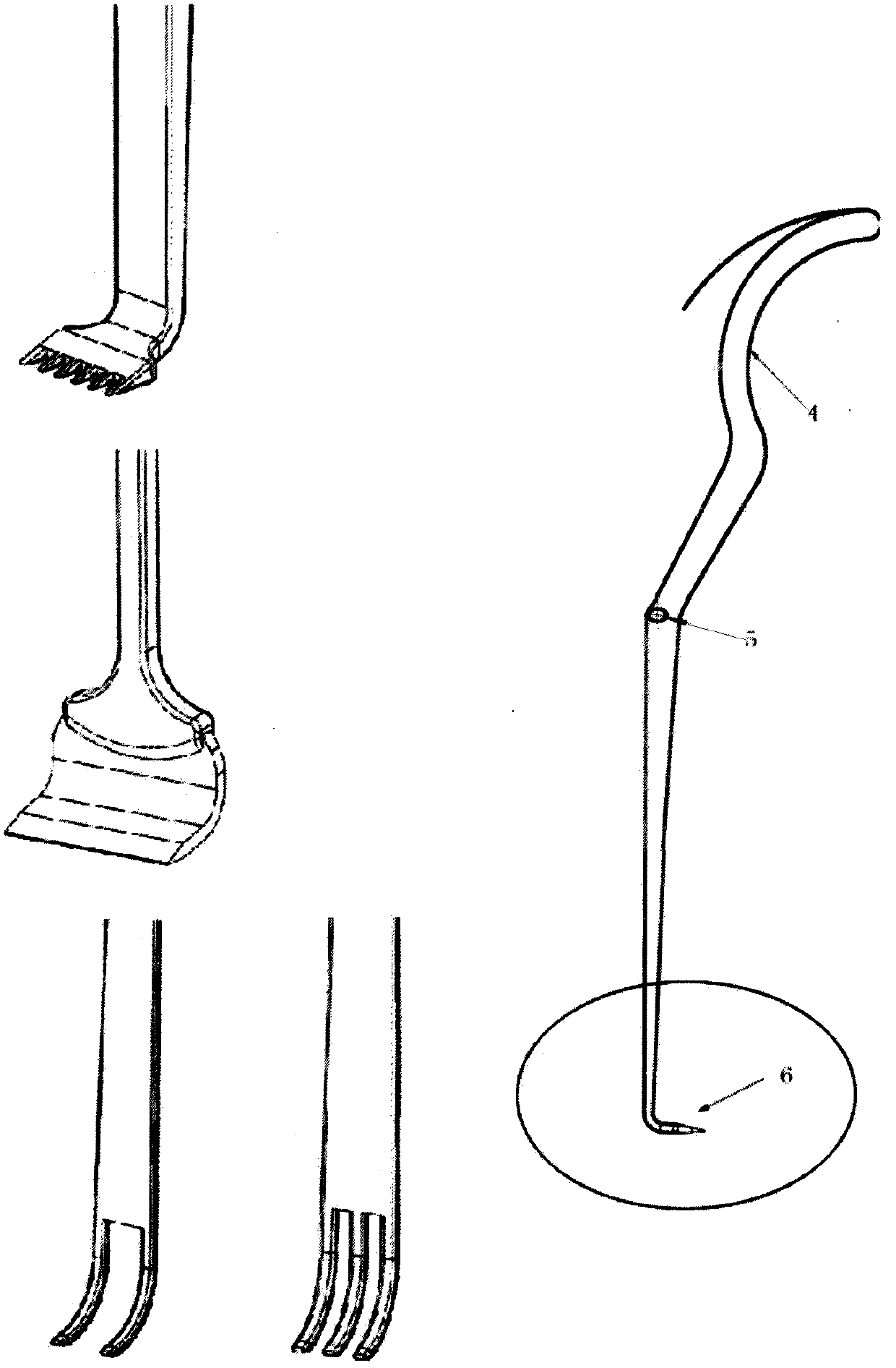
[0036] see Figure 4 , In the second embodiment, the foot of the first rod in the first embodiment is changed, it is no longer a right-angle bent plate 3, but is welded by the vertical foot part and the oblique foot part. The oblique foot part is welded together with the lower part of the first rod, and its function is the same as that of the right-angled bent plate 3, and it also bears against the bone edge section of the skull, and plays the role of a support point during the operation. Alternatively, the foot of the first rod is a vertical plate structure with horizontal bifurcations. During the operation, the vertical part of the vertical plate structure abuts against the section of the bone margin of the skull, while the horizontal bifurcation is placed flat on the bone margin of the skull. On the horizontal plane, a snap fit is formed, which acts as a support point during the operation.

no. 3 example

[0038] see Figure 5 , in the third embodiment, the foot of the second rod in the first embodiment is changed, it is no longer a shovel shovel 6, but a multi-tooth shovel, wherein the number of teeth of the multi-tooth shovel is two one or more. The bifurcated portion of the shovel teeth can be bifurcated from the vertical bar at the bottom of the second bar, or can be further bifurcated on a horizontal plane perpendicular to the vertical bar of the second bar.


PUM

PropertyMeasurementUnit
Heightaaaaaaaaaa

Abstract

The invention relates to a novel scalp dilator special for a skull defect repair surgery. The novel scalp dilator is of a joint plier structure, and composed of a first rod part and a second rod part,and the first rod part and the second rod part are connected through movable shaft holes. The foot part of the first rod part is a right-angle bending plate, the right-angle bending plate is used forsearching and being attached to the skull fracture surface in the surgery, and can change the skull bone edge covered with proliferating granulation tissue into a visual marker. The foot part of thesecond rod part is of a milling shovel structure with a 90-degee rounded angle with a main body, and the foot part of the second rod part is used for extending into a scalp to raise the scalp. Duringthe surgery, a surgeon only needs to abut the foot part of the first rod part against the skull fracture surface, force is applied by fingers to close a handle, the foot part of the first rod part andthe foot part of the second rod part are separated through the lever effect, the scalp edge can be raised, and thus the cutting position can be quickly determined.

Description

technical field [0001] The invention relates to a new type of scalp spreader, which is used in neurosurgical skull defect repair operation, which is convenient for doctors to quickly locate the bone edge of the skull covered by hyperplastic tissue, prevents accidental injury of brain tissue during operation, speeds up operation speed and improves operation efficiency. safety. Background technique [0002] For patients with traumatic brain injury, brain tumor and cerebral hemorrhage, during the first craniotomy, due to swelling of the brain tissue, the patient's skull cannot be reset. At this time, the doctor will directly suture the scalp to achieve the purpose of bony decompression and release intracranial pressure. Ensure patient safety after surgery. Especially for patients with severe craniocerebral trauma, decompressive large bone craniectomy is recognized as an effective surgical method, so most patients with traumatic brain trauma will leave postoperative skull defec...

Claims


Application Information

Patent Timeline
IPC IPC(8): A61B17/02
Inventor 杨岸超徐珑张建国
Owner BEIJING NEUROSURGICAL INST
Why Eureka
Try Eureka