Pulse discharge flash sintering metal-based part near-net forming technology method
A technology of pulse discharge and sintering metal, which is applied in the field of powder metallurgy, can solve the problems of insufficient attention to technology and achieve the effects of simplified process flow, low power utilization rate and high product quality
- Summary
- Abstract
- Description
- Claims
- Application Information
AI Technical Summary
Problems solved by technology
Method used
Image
Examples
Embodiment 1
[0042] a. Calculating the powder loading amount of metal powder for manufacturing iron-based gears through the theoretical powder density;
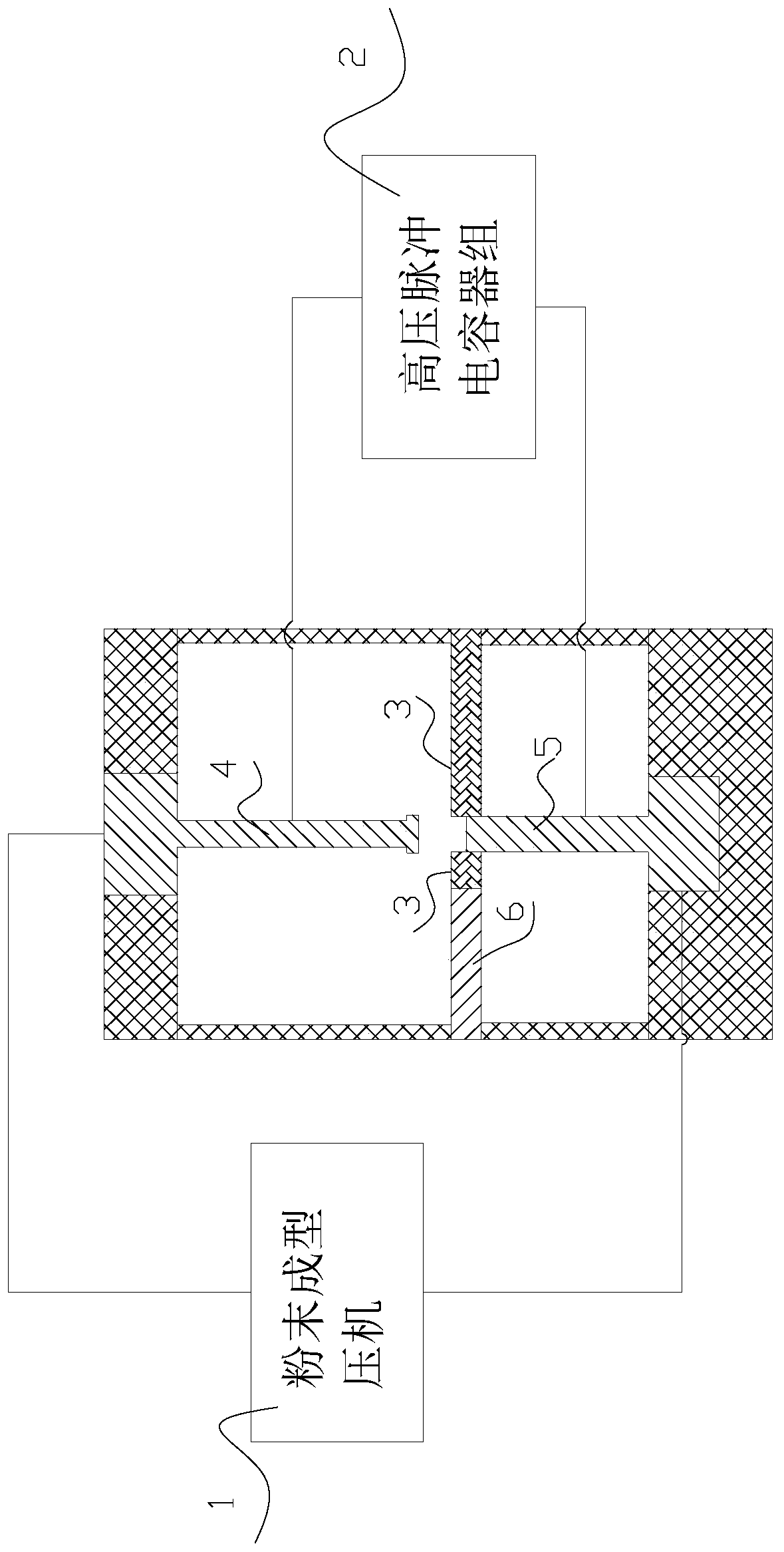
[0043] b. Prepare the mold 3 and die punch matched with the iron-based gear in advance, push the metal powder in step a into the mold 3 by the feeding device 6, and shape the metal powder by the die punch; use the die punch as The electrode of the pulse discharge body, which performs pulse discharge synchronously on the metal powder during the molding process; that is, the die punch includes the upper die punch 4 and the lower die punch 5, and the upper die punch 4 and one of the electrodes of the pulse capacitor bank 2 Electrical connection, the lower die punch 5 is electrically connected to the other electrode of the pulse capacitor bank 2; the pulse capacitor bank 2 is charged during the metal powder pushing process and / or the mold punching and ejection process; the pulse current waveform generated by the discharge of the pulse capacito...
Embodiment 2
[0049] a. Calculating the powder loading amount of metal powder for manufacturing iron-based gears through the theoretical powder density;
[0050] b. Prepare the mold 3 and die punch matched with the iron-based gear in advance, push the metal powder in step a into the mold 3 by the feeding device 6, and shape the metal powder by the die punch; use the die punch as The electrode of the pulse discharge body, which performs pulse discharge synchronously on the metal powder during the molding process; that is, the die punch includes the upper die punch 4 and the lower die punch 5, and the upper die punch 4 and one of the electrodes of the pulse capacitor bank 2 Electrical connection, the lower die punch 5 is electrically connected to the other electrode of the pulse capacitor bank 2; the pulse capacitor bank 2 is charged during the metal powder pushing process and / or the mold punching and ejection process; the pulse current waveform generated by the discharge of the pulse capacito...
Embodiment 3
[0055] a. Calculating the powder loading amount of metal powder for manufacturing iron-based gears through the theoretical powder density;
[0056] b. Prepare the mold 3 and die punch matched with the iron-based gear in advance, push the metal powder in step a into the mold 3 by the feeding device 6, and shape the metal powder by the die punch; use the die punch as The electrode of the pulse discharge body, which performs pulse discharge synchronously on the metal powder during the molding process; that is, the die punch includes the upper die punch 4 and the lower die punch 5, and the upper die punch 4 and one of the electrodes of the pulse capacitor bank 2 Electrical connection, the lower die punch 5 is electrically connected to the other electrode of the pulse capacitor bank 2; the pulse capacitor bank 2 is charged during the metal powder pushing process and / or the mold punching and ejection process; the pulse current waveform generated by the discharge of the pulse capacito...
PUM
| Property | Measurement | Unit |
|---|---|---|
| diameter | aaaaa | aaaaa |
| thickness | aaaaa | aaaaa |
| density | aaaaa | aaaaa |
Abstract
Description
Claims
Application Information
 - R&D
- Intellectual Property
- Life Sciences
- Materials
- Tech Scout
- Unparalleled Data Quality
- Higher Quality Content
- 60% Fewer Hallucinations
Browse by: Latest US Patents, China's latest patents, Technical Efficacy Thesaurus, Application Domain, Technology Topic, Popular Technical Reports.
© 2025 PatSnap. All rights reserved.Legal|Privacy policy|Modern Slavery Act Transparency Statement|Sitemap|About US| Contact US: help@patsnap.com

