Bio-organic fertilizer crushing apparatus
A bio-organic fertilizer and crushing device technology, which is applied in the direction of raw material extrusion and granulation, can solve the problems of insufficient compactness inside the granular organic fertilizer, moisture deterioration of the organic fertilizer, and agglomeration of the organic fertilizer, so as to avoid incomplete crushing of raw materials , realize the uniformity of feeding, and avoid the effect of device blockage
- Summary
- Abstract
- Description
- Claims
- Application Information
AI Technical Summary
Problems solved by technology
Method used
Image
Examples
Embodiment 1
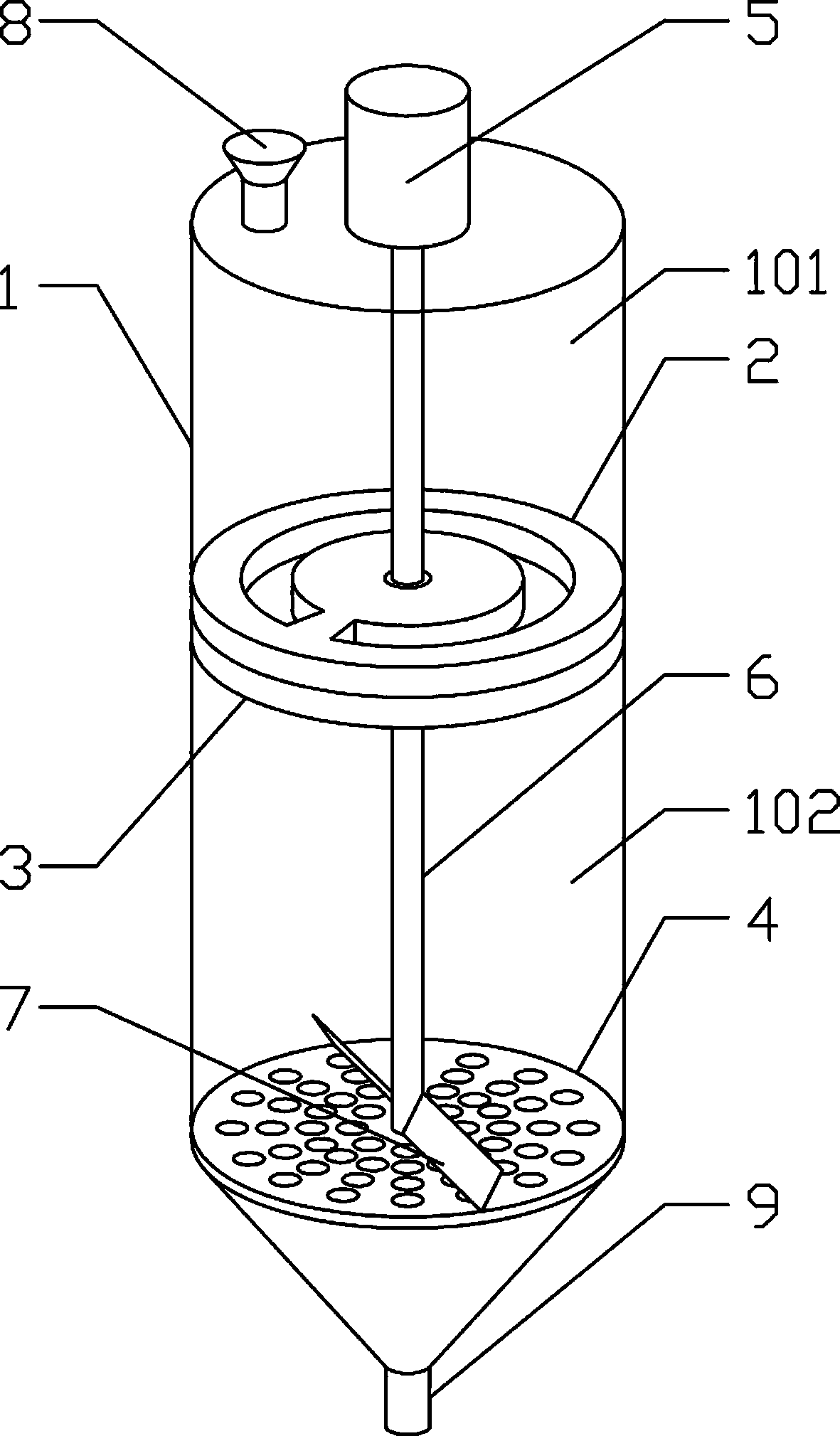
[0026] Such as figure 1 Among them, a bio-organic fertilizer crushing device includes a cylinder body 1, and the cylinder body 1 is provided with a collection bin fixed bottom plate 2, and the collection bin fixed bottom plate 2 separates the cylinder body 1 to form two upper and lower chambers, and the collection bin is fixed The cylinder body 1 above the bottom plate 2 is a collection bin 101, and the cylinder body 1 below the fixed bottom plate 2 of the collection bin is a crushing bin 102;
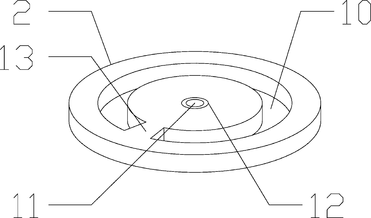
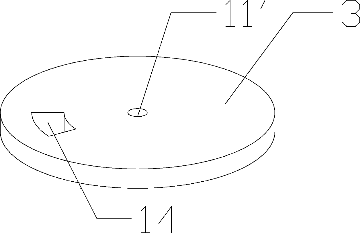
[0027] The fixed bottom plate 2 of the collecting bin is provided with a first feeding hole 10, and the movable bottom plate 3 of the collecting bin is provided under the fixed bottom plate 2 of the collecting bin, and the movable bottom plate 3 of the collecting bin is provided with a second feeding port 14. ;
[0028] The crushing chamber 102 is provided with a crushing plate 4, and the crushing plate 4 is provided with a plurality of extrusion holes 15;
[0029] The top of the cyl...
Embodiment 2
[0031] On the basis of embodiment 1, the fixed bottom plate 2 of the collection bin is provided with a shaft hole 11 for the shaft 6 to pass through, and the shaft hole 11 is provided with a bearing 12, and the movable bottom plate 3 of the collection bin is also provided with There is a rotating shaft hole 11 for the rotating shaft 6 to pass through, and the movable bottom plate 3 of the collecting bin is fixedly connected with the rotating shaft 6 .
[0032] In the preferred solution, the fixed bottom plate 2 of the collecting bin is provided with a connecting block 13, and the connecting block 13 connects the middle part of the fixed bottom plate 2 of the collecting bin with the periphery and forms an annular first discharge hole 10. The second feeding port 14 provided on the movable bottom plate 3 of the silo is the same size and shape as the connecting block 13 .
Embodiment 3
[0034] On the basis of Embodiment 1, there are two extruding plates 7, 180° between the two extruding plates 7, and the extruding plates 7 are inclined, and the rotating shaft 6 is formed by the extruding plates 7 and the crushing plates 4 The side at an obtuse angle rotates toward the side at which the extruding plate 7 and the crushing plate 4 form an acute angle.
[0035] In an optional solution, there are two cutting blades 16, the distance between the two cutting blades 16 is 180°, and the two cutting blades 16 and the two extrusion plates 7 are arranged alternately at 90°.
PUM
 Abstract
Description
Claims
Application Information
 - R&D
- Intellectual Property
- Life Sciences
- Materials
- Tech Scout
- Unparalleled Data Quality
- Higher Quality Content
- 60% Fewer Hallucinations
Browse by: Latest US Patents, China's latest patents, Technical Efficacy Thesaurus, Application Domain, Technology Topic, Popular Technical Reports.
© 2025 PatSnap. All rights reserved.Legal|Privacy policy|Modern Slavery Act Transparency Statement|Sitemap|About US| Contact US: help@patsnap.com


