Low-k dielectric composition for high frequency applications
A technology of dielectric materials and dielectric constants, applied in circuits, electrical components, printed circuits, etc., can solve problems such as high working temperature, inability to handle, low mechanical strength, etc.
- Summary
- Abstract
- Description
- Claims
- Application Information
AI Technical Summary
Problems solved by technology
Method used
Image

Examples
Embodiment
[0073] The following examples in Tables 5A-5B are provided to illustrate preferred aspects of the invention and are not intended to limit the scope of the invention.
[0074] To further evaluate the various aspects and benefits of the inventive subject matter, a series of studies were conducted to evaluate dielectric materials and fired dielectric devices formed from the dielectric materials in accordance with the inventive subject matter. Table 5A below shows the expected range of glass component oxides, and the glass component oxides present in Example 1 and Example 2 prepared in accordance with the inventive subject matter.
[0075] Table 5A
[0076]
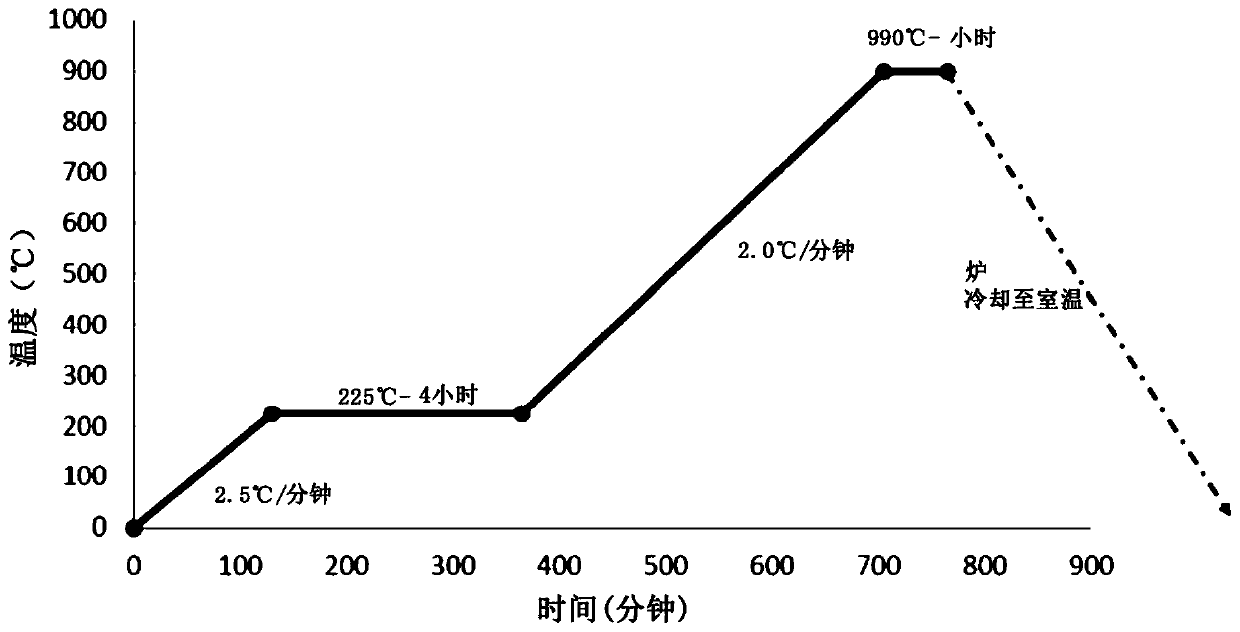
[0077] In Table 5A, Example 1 was fired at a peak temperature of 900°C for 1 hour, and Example 2 was fired at a peak temperature of 850°C for 1 hour, both of which contained 3.5 grams of the glass component (or glass material) and 1.5 grams of amorphous silicon dioxide. Example 2 also contained 0.6 grams (approximately 1...
Embodiment 2
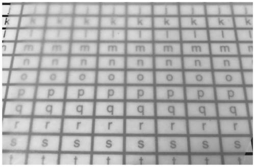
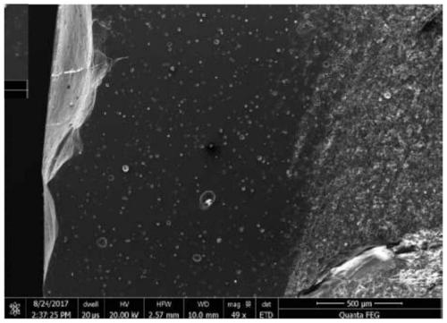
[0080] Example 2 is fired at 850°C to form a transparent dielectric layer, such as Figure 7 As shown, its thickness is 0.19mm, the sintered density is 86.5%, the Q value at 10GHz is 2697.8, and the loss tangent value is 1.71×10 -2 , the K value at 10GHz is 3.74. The SEM figure of embodiment 2 is shown in Figure 8 and Figure 9 middle.
[0081] A comparative example was prepared by firing only the glass component (EG2790 available from Ferro Corporation) without adding any silica powder. The comparative example was fired at 700°C to produce Figure 10 The transparent 0.16mm thick dielectric layer shown has a Q value of 9021.7 at 10GHz and a loss tangent of 2.91×10 -3 , the K value at 10GHz is 3.14. Although the comparative example has a high Q value and a low K value, it is believed that the silver migration in the comparative example will be greater than that in the inventive examples 1 and 2, which can be problematic when co-fired with silver conductors in LTCC applicat...
Embodiment 3
[0086] Example 3 also includes 0.4 grams (about 4% by weight) of nano-silica and 0.8 grams of Al 2 o 3 (about 8% by weight), while Example 4 also included 1.2 grams (about 12% by weight) of Al 2 o 3 .
[0087] As mentioned above, increasing the mechanical strength of the sintered dielectric material can be important for a robust substrate. In Example 3 and Example 4, various strength additives can be added, and compared with Example 1, the strength is improved. The strength value of Example 1 is 95.2 MPa, while the strength values of Example 3 and Example 4 are 135.8 MPa and 128.6 MPa, respectively. This increase in strength can be attributed to the reduction of pores in the samples and the addition of high Young's modulus fillers.
[0088] The inventive subject matter can be further explained in the following items:
[0089] Item 1 - A sintered dielectric material comprising, prior to sintering, a solid portion comprising 10% to 99% by weight of D-50 silica powder hav...
PUM
| Property | Measurement | Unit |
|---|---|---|
| Thickness | aaaaa | aaaaa |
| Coefficient of expansion | aaaaa | aaaaa |
| Coefficient of expansion | aaaaa | aaaaa |
Abstract
Description
Claims
Application Information
 - R&D
- Intellectual Property
- Life Sciences
- Materials
- Tech Scout
- Unparalleled Data Quality
- Higher Quality Content
- 60% Fewer Hallucinations
Browse by: Latest US Patents, China's latest patents, Technical Efficacy Thesaurus, Application Domain, Technology Topic, Popular Technical Reports.
© 2025 PatSnap. All rights reserved.Legal|Privacy policy|Modern Slavery Act Transparency Statement|Sitemap|About US| Contact US: help@patsnap.com