
CO2 displacement experimental system and experimental method

A technology for displacement experiments and CO2, which is applied in the field of CO2 displacement experiment systems, can solve the problems of large experimental errors and large fluctuations in injection pressure, and achieve the effect of easy operation and stable control pressure

Pending Publication Date: 2019-06-25
CHINA HUANENG GRP CO LTD +1
View PDF0 Cites 3 Cited by
  • Summary
  • Abstract
  • Description
  • Claims
  • Application Information

AI Technical Summary

Problems solved by technology

[0003] However, the existing displacement experiment system is only aimed at gas phase displacement or liquid phase displacement, or the injection pressure fluctuates greatly, resulting in large experimental errors and unable to satisfy CO2 displacement at the same time. 2 The process of two-phase seepage and displacement with water (or aqueous solution, or hydraulic fracturing fluid) in the reservoir

Method used


Image

  • CO2 displacement experimental system and experimental method

Examples


Embodiment Construction

[0045] The implementation of the present invention will be described in detail below in conjunction with the drawings and examples.

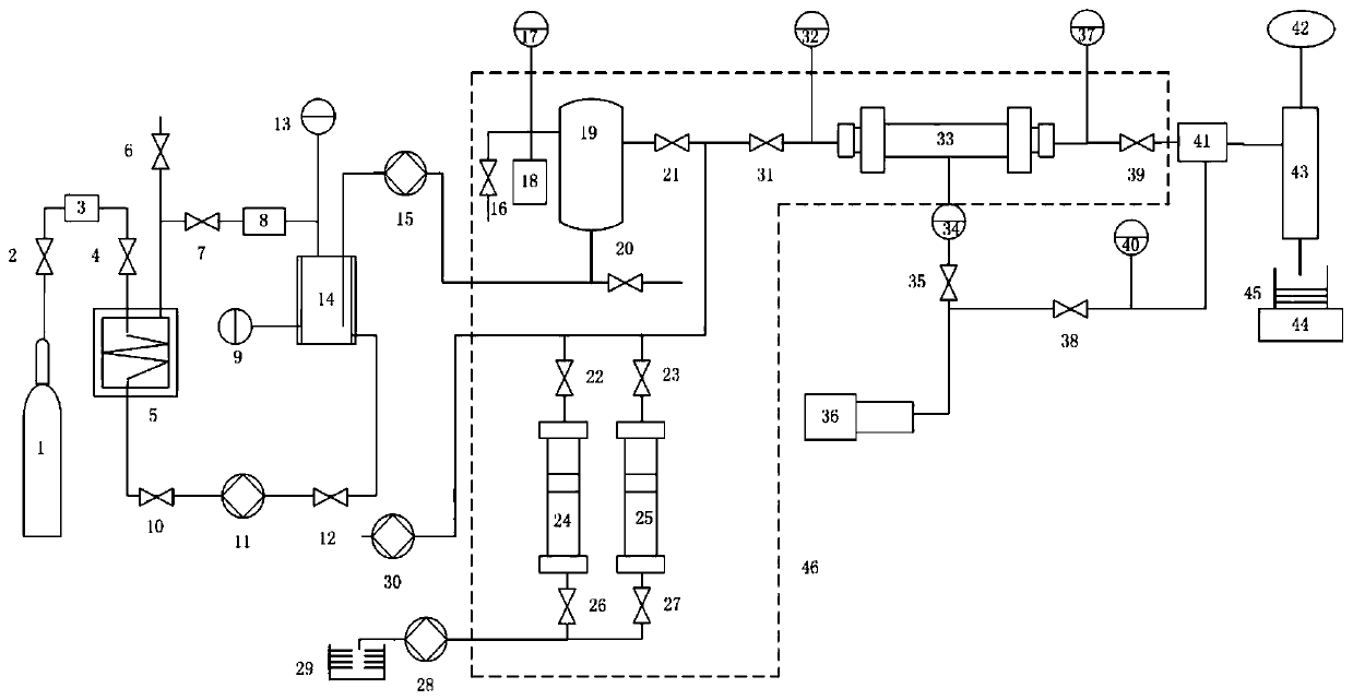
[0046] Such as figure 1 As shown, the present invention provides a CO 2 Displacement experiment system, including gas refrigeration system, vacuum system, gas injection system, liquid injection system, core clamping system, loop pressure system and metering system.

[0047] The gas refrigeration system consists of CO 2 Cylinder 1, first valve 2, purifier 3, second valve 4, cooling water bath 5, fifth valve 10, first CO 2 The pump 11, the sixth valve 12, and the storage tank 14 are sequentially connected to form. In addition, the cooling water bath 5 is connected to the top of the storage tank 14 through the fourth valve 7 and the filter 8 in sequence. A venting branch controlled by a third valve 6 is also designed on the top of the cooling water bath 5 . The top of the storage tank 14 is designed with a first pressure gauge 13 and a thermom...


PUM


Abstract

The invention discloses a CO2 displacement experimental system and experimental method. The system comprises a gas refrigeration system, a gas injection system, a liquid injection system and a core clamping system. The gas refrigeration system is composed of a gas cylinder filled with CO2, a purifier, a refrigeration water bath, a first CO2 pump and a storage tank, wherein the gas cylinder filledwith CO2, the purifier, the refrigeration water bath, the first CO2 pump and the storage tank are sequentially connected. The gas injection system is sequentially connected with a second CO2 pump anda buffer tank through the storage tank. The liquid injection system comprises two branches connected in parallel. The first branch comprises a first piston container. The second branch comprises a second piston container. The inlet of the liquid injection system is sequentially connected with a liquid injection pump and a first container. The outlet is connected with the buffer tank. The core clamping system comprises a core holder. The core holder is connected with the gas injection system and the liquid injection system. The device provided by the invention can simulate and test the displacement process of carbon dioxide or an aqueous solution to the reservoir core under different displacements, different temperatures, different pressures and different solution ratios, and calculates residual water saturation or residual CO2 saturation.

Description

technical field [0001] The invention belongs to the technical field of carbon dioxide and water multiphase flow, in particular to a CO 2 Displacement experimental system and experimental method. Background technique [0002] In recent years, carbon dioxide anhydrous fracturing technology, CO 2 displacement of unconventional natural gas, and CO 2 Geological storage and other related technologies are gradually becoming the focus of current research. They all relate to the CO 2 The process of two-phase seepage or displacement with water (or aqueous solution, or hydraulic fracturing fluid) in a reservoir. [0003] However, the existing displacement experiment system is only aimed at gas phase displacement or liquid phase displacement, or the injection pressure fluctuates greatly, resulting in large experimental errors, and cannot meet the requirements of CO2 displacement at the same time. 2 The process of two-phase seepage and displacement with water (or aqueous solution, o...

Claims


Application Information

Patent Timeline
IPC IPC(8): G01N5/02
Inventor 张健张国祥王金意荆铁亚赵文韬
Owner CHINA HUANENG GRP CO LTD
Learn More