Method for determining a beam profile of a laser beam, and processing machine

A beam profile and processing machine technology, used in additive processing, manufacturing, photometry, etc., can solve the problems of large installation space of measuring instruments, high time consumption, and inability to perform beam profile determination.

Active Publication Date: 2019-06-25
TRUMPF LASERSYST FOR SEMICON MFG
View PDF17 Cites 4 Cited by
  • Summary
  • Abstract
  • Description
  • Claims
  • Application Information

AI Technical Summary

Problems solved by technology

Since the processing chamber is normally not accessible from the outside, the time expenditure required for mounting and dismantling the measuring instrument and for the actual measurement is enormous and can be several hours
Furthermore, the determination of the beam profile cannot be carried out during operation of the processing machine, since the measuring instrument requires a large installation space

Method used


Image

  • Method for determining a beam profile of a laser beam, and processing machine
  • Method for determining a beam profile of a laser beam, and processing machine
  • Method for determining a beam profile of a laser beam, and processing machine

Examples


Embodiment Construction

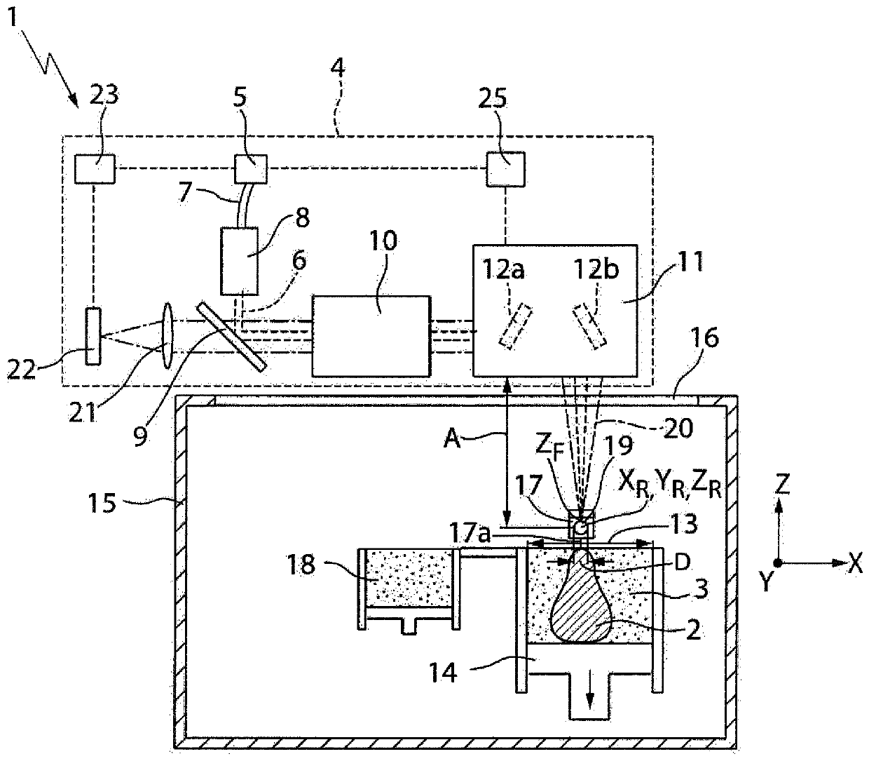
[0040] figure 1 An exemplary structure of a processing machine 1 for producing a three-dimensional component 2 by irradiating a powder layer 3 in figure 1In the example shown, they are arranged one above the other and form a powder bed in which the three-dimensional component 2 is embedded. The processing machine 1 has an irradiation device 4 with a laser source 5 in the form of a fiber laser for generating a laser beam 6 which is guided via an optical cable 7 and a collimation device 8 to a deflecting mirror 9 superior. In the example shown, the laser beam 6 is a high-power processing laser beam which is used to irradiate or melt the powder layer 3 locally. Alternatively, the laser beam 6 can be a pilot laser beam which is also generated by the laser source 5 in the form of a fiber laser. In the example shown, the processing laser beam 6 has a different wavelength than the pilot laser beam. exist figure 1 In the example 1 shown, the deflection mirror 9 has a dielectric c...


PUM

PropertyMeasurementUnit
diameteraaaaaaaaaa
refractive indexaaaaaaaaaa
reflectanceaaaaaaaaaa

Abstract

The invention relates to a method for determining a beam profile of a laser beam (6), which is positioned by means of a scanner device (11) in a processing field (13), comprising: arranging at least one retroreflector (19) in the processing field (13) of the scanner device (11), which area is preferably formed in a processing chamber (15) for irradiating powder layers (3), detecting laser radiation (20) which, during scanning travel over the retroreflector (19) with the laser beam (6), is reflected back into the scanner device (11), and determining the beam profile of the laser beam (6) by using the laser radiation (20) detected during the scanning travel over the retroreflector (19). The invention further relates to an associated processing machine (1) for producing three-dimensional components (2) by means of the irradiation of powder layers (3).

Description

technical field [0001] The invention relates to a method for determining a beam profile of a laser beam which is positioned in a processing area by means of a scanning device. The invention also relates to a processing machine for producing three-dimensional components by irradiating powder layers. Background technique [0002] For laser processing it is advantageous if the beam profile of the laser beam, ie the location-dependent intensity distribution or power distribution of the laser beam perpendicular to the direction of propagation of the laser beam, is determined or precisely detected. Knowing the beam profile on or in the vicinity of the machining plane, in which the laser beam is usually focused for machining, is particularly advantageous. In or near the processing plane, for example in the case of laser processing machines, the workpiece can be arranged or, in the case of processing machines for producing three-dimensional components, the powder layer to be irradi...

Claims


Application Information

Patent Timeline
Patent Type & Authority Applications(China)
IPC IPC(8): B22F3/105G01S5/16G05B19/401B33Y10/00B33Y30/00B33Y50/02B29C64/00
CPCB22F2999/00B33Y10/00B33Y30/00B33Y50/02G01B11/00B29C64/153B29C64/268Y02P10/25B22F10/31B22F12/90B22F10/28B22F12/60B23K26/0006B23K26/342B23K26/082B23K26/705B22F12/49B22F12/41B22F12/44B22F12/224B22F2203/03G01J1/0407G01J1/4257G01J1/44G01J2001/446G02B5/126
Inventor M·阿伦贝里-拉贝P·瓦根布拉斯特
Owner TRUMPF LASERSYST FOR SEMICON MFG
Why Eureka
Try Eureka