EHF frequency band microwave network device

A microwave network and frequency band technology, applied in the field of satellite communications, can solve the problems that microwave networks cannot withstand the use of high power, the overall microwave network architecture is large, and the debugging of ultra-high frequencies is difficult. small pop effect

Pending Publication Date: 2019-06-28
SHAANXI EVSAT SCI & TECH DEV
View PDF0 Cites 0 Cited by
  • Summary
  • Abstract
  • Description
  • Claims
  • Application Information

AI Technical Summary

Problems solved by technology

[0003] 1. The traditional UHF microwave network adopts microstrip mode for transmission, coupling and power division, but this form of microwave network cannot withstand the use of high power;
[0004] 2. When the traditional ultra-high frequency microwave network is designed with a cavity method, the polarizer adopts a cross-tooth polarizer. This form is difficult to guarantee performance through processing, and it is difficult to debug due to ultra-high frequency during manual debugging;
[0005] 3. When the traditional UHF microwave network is designed in the form of a cavity, most of them are asymmetrical structures, which ar...

Method used


Image

  • EHF frequency band microwave network device
  • EHF frequency band microwave network device
  • EHF frequency band microwave network device

Examples


Embodiment 1

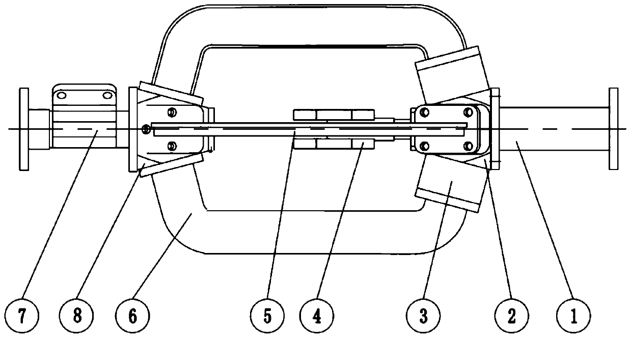
[0059] Embodiment 1: A microwave network device in the EHF frequency band, see Figure 1 to Figure 13 ;include:

[0060] A wave splitter 2 with six ports;

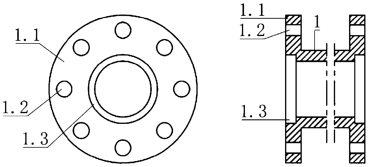
[0061] a waveguide 1;

[0062] Four Q / K band cavity filters 3;

[0063] Two +45° phase shifters 5;

[0064] Two -45° phase shifters 6;

[0065] a combiner 8 with five ports;

[0066] a bulkhead polarizer 4;

[0067] A K-band quadrature-mode coupler 7 .

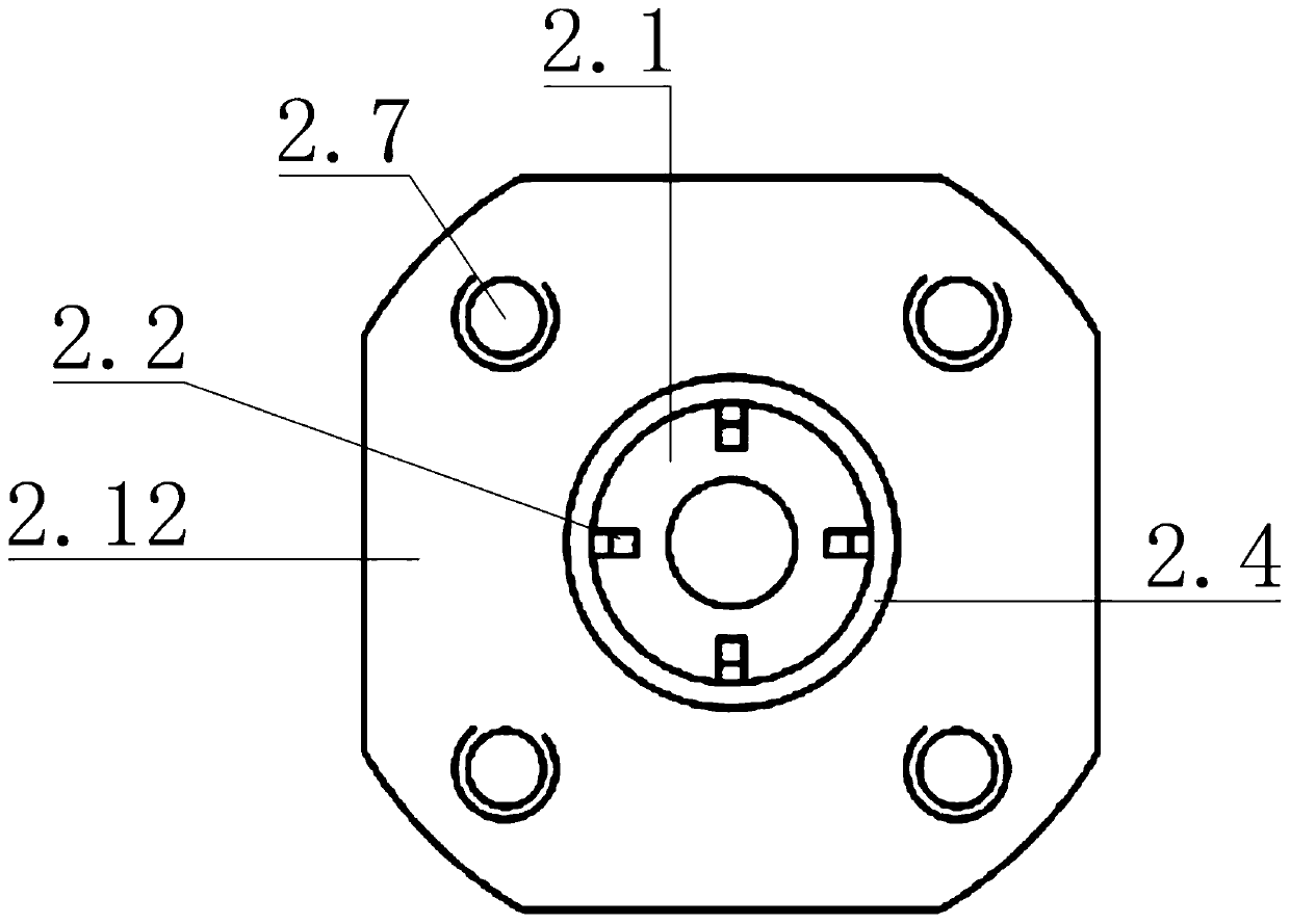
[0068] Specifically, the axial section of the wave splitter 2 is trapezoidal, and the front side 2.15 and the rear side, the upper side 2.11 and the lower side 2.13 of the wave splitter are all symmetrical structures, and the front side 2.15, the rear side, and the upper side 2.11 has the same structure as the lower side 2.13; the wave splitter is equipped with a conical cavity 2.1 to ensure electrical conduction, and the conical cavity 2.1 runs through the left and right ends of the conical cavity along the axial direction of the wave splitter, and the conical cavi...


PUM


Abstract

The invention provides an EHF frequency band microwave network device with a novel structural design. The device comprises a wave separator provided with six ports; Four Q/K frequency band cavity filters; two + 45 DEG phase shifters; two-45 DEG phase shifters; a combiner provided with five ports; a separator polarizer; and a K-band orthogonal mode coupler. The four Q/K frequency band cavity filters are respectively connected to a front side port, a rear side port, an upper side port and a lower side port of the wave separator. One end of the two +45 DEG phase shifters in the same direction are respectively connected to the two Q/K frequency band cavity filters, and the other ends of the two +45 DEG phase shifters are respectively connected to the combiner. One end of the two -45 DEG phase shifters in the same direction is connected to the two Q/K frequency band cavity filters, the other end of the 45-degree phase shifter is connected to the combiner, and the separator polarizer is connected to a left side port of the wave separator. The K-band orthogonal mode coupler is connected to a left side port of the combiner. A circular waveguide is connected to the port of the right sidesurface of the wave separator.

Description

technical field [0001] The invention relates to the field of satellite communication, in particular to an EHF frequency band microwave network device for an EHF frequency band satellite communication antenna. Background technique [0002] In recent years, with the changes in the international political and economic situation and the rapid development of semiconductor microelectronics technology, the status of satellite communication technology has become more and more important, especially the high-frequency millimeter-wave frequency band satellite communication system, which has become the development goal of various countries . As a part of the millimeter-wave frequency band, the EHF frequency band has also attracted more attention from various countries, so the development of radio frequency equipment in the EHF frequency band is becoming more and more urgent. Under the premise of the international environment, military applications, civilian needs and the gradual maturi...

Claims


Application Information

Patent Timeline
IPC IPC(8): H04B1/40
Inventor 艾宇涛杨文涛
Owner SHAANXI EVSAT SCI & TECH DEV
Why Eureka
Try Eureka