
A heat-proof layer forming tool for the side wall of a returnable spacecraft

A returnable airship and forming tooling technology, which is applied to household appliances, other household appliances, household components, etc., can solve the problems of inability to monitor the impregnation of the heat-resistant layer, damage, and waste of resin in real time, so as to improve the overall thermal protection performance. The effect of reducing complexity and reducing the number of blocks

Active Publication Date: 2020-12-18
BEIJING SATELLITE MFG FACTORY
View PDF5 Cites 0 Cited by
  • Summary
  • Abstract
  • Description
  • Claims
  • Application Information

AI Technical Summary

Problems solved by technology

[0005] (1) The size of the heat-resistant layer formed by conventional forming tooling is generally less than 1m. When the heat-resistant layer is used, multiple pieces are spliced ​​to achieve the overall coverage of the heat protection area. This method cannot be applied to the reentry spacecraft returning to the re-entry heat flow at the second space flight speed. Requirements of the environment for the integral molding of the side wall heat protection layer
[0006] (2) Due to the low strength of the material and the easy deformation of the heat-resistant layer on the side wall of the reversible spacecraft, the conventional forming tooling is transferred and turned over the heat-resistant layer, which cannot ensure that the heat-resistant layer is uniformly stressed. too large, deformed
[0007] (3) Conventional molding tooling does not have a device to prevent the heat-resistant layer from floating during resin impregnation. The fiber-reinforced low-density thermal protection material has a low density. When resin is impregnated, the material is affected by the buoyancy of the liquid resin and floats, which in turn causes material deformation.
[0008] (4) Conventional molding tooling has a small number of heat-resistant layers in a single molding, and the heat-resistant area on the side wall of the returnable spacecraft is large, and multiple pieces are required for assembly. The single-piece preparation method is used, and the manufacturing cycle is long.
[0009] (5) Conventional molding tooling cannot monitor the impregnation of the heat-proof layer in the resin in real time, and it is not convenient to judge the resin impregnation result
[0010] (6) Conventional molding tooling adopts the resin impregnation method in which resin is injected from the top of the tooling, which is easy to block air in the heat-resistant layer and form defects
[0011] (7) Conventional molding tooling has no demoulding guarantee measures. The heat-resistant layer of the side wall of the reversible spacecraft is a non-closed cone, which is easily deformed by force. After curing, the structural form will be difficult to demould, and forced demoulding will cause heat protection. Layer damage, even destruction
[0012] (8) Conventional molding tooling has a regular inner cavity, and after the heat-resistant layer of the side wall of the returnable spacecraft with a curved surface structure is placed in it, there will be a large gap between the heat-resistant layer and the tooling. When the resin is impregnated, the gap will be filled by the resin. A lot of resin is wasted, which increases the manufacturing cost

Method used


Image

  • A heat-proof layer forming tool for the side wall of a returnable spacecraft
  • A heat-proof layer forming tool for the side wall of a returnable spacecraft
  • A heat-proof layer forming tool for the side wall of a returnable spacecraft

Examples


Embodiment Construction

[0052] The present invention will be further described below in conjunction with the accompanying drawings and embodiments.

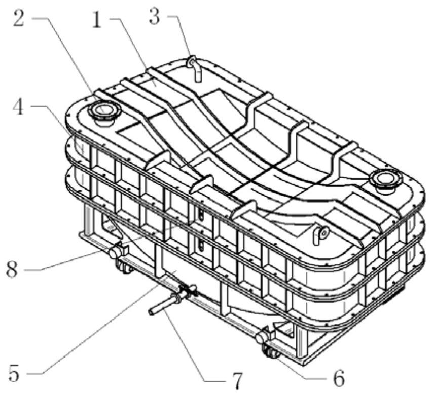
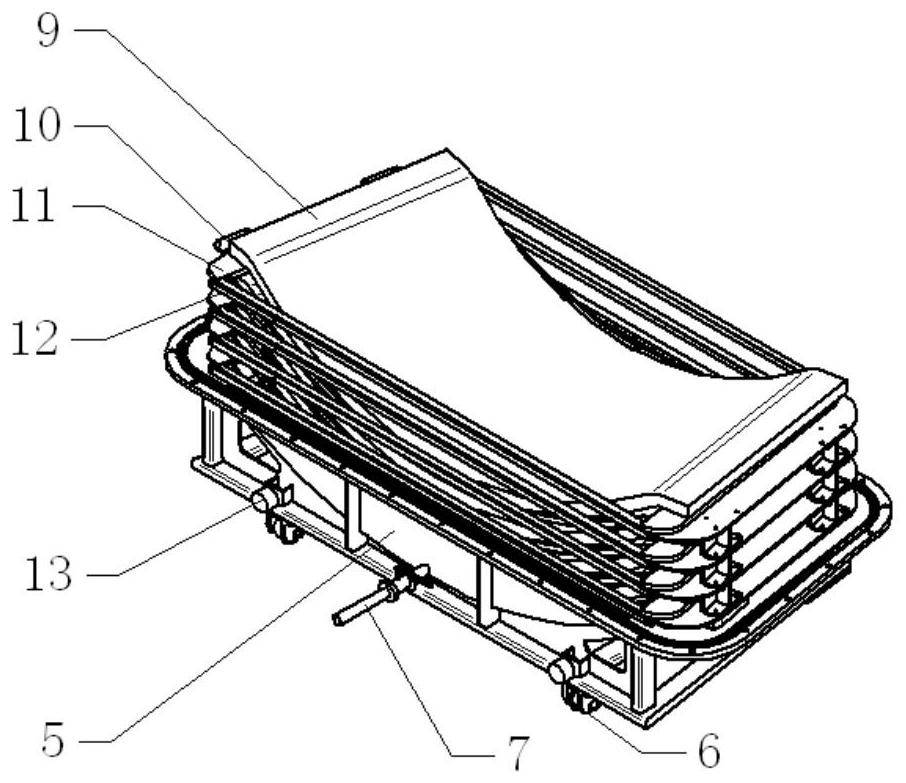
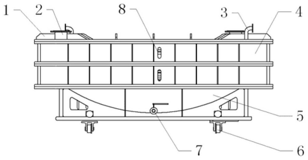
[0053] Such as Figure 1 to Figure 7 As shown, a heat-proof layer forming tool for the side wall of a returnable spacecraft includes an upper mold 1, a middle mold 4, a lower mold 5, a guide wheel 6, a tray 12, a lifting ring 11, an upper mold observation window 2, and a middle mold observation window 8. Temperature sensor 16, glue injection pipeline 7, vacuum pipeline 3, compression frame 15, support seat 10, compression plate 14, crash pad 13; along the height direction, the tooling is divided into four layers, upper mold 1, middle mold 4. The lower mold 5, wherein the middle mold 4 has two layers; the middle mold 4 and the lower mold 5 are used to hold the heat-proof layer 9 on the side wall of the spaceship; the installation surface between the middle mold 4 and the lower mold 5 is in the height direction of the inner tray 12 The middle position; t...


PUM

PropertyMeasurementUnit
widthaaaaaaaaaa
heightaaaaaaaaaa
lengthaaaaaaaaaa

Abstract

The invention discloses a returning type airship side wall heat shielding layer forming tool. The returning type airship side wall heat shielding layer forming tool comprises an upper mold, a middle mold, a lower mold, a tray, a lifting ring, an upper mold observing window, a temperature sensor, a glue injection pipeline, a vacuum pipeline, a pressing frame, a supporting base, a pressing plate anda heat shielding layer. In the height direction, the upper mold, the middle mold and the lower mold are arranged; the middle mold and the lower mold are used for containing the airship side wall heatshielding layer, the mounting face between the middle mold and the lower mold is arranged in the middle position in the height direction of an inner tray, the upper mold serves as an upper cover, andafter assembling, a closed cavity is jointly formed by the upper mold, the middle mold and the lower mold. The problem that a fiber enhanced low-density protection material is prone to deforming is solved, material lifting, transferring and turnover in the preparing process can be achieved, it is ensured that after the material is formed, the conical shape of the returning type airship heat proofside wall is directly formed, and multiple pieces are prepared through one time.

Description

technical field [0001] The invention relates to a molding tool, which belongs to the field of molding of fiber-reinforced low-density thermal protection materials. Background technique [0002] Due to the need to experience high heat flow erosion during the reentry flight, the outer surface of the returnable spacecraft must have a reliable, erosion-resistant thermal protection system to protect the equipment and personnel inside the spacecraft. With the continuous development of deep space exploration projects, the return of the spacecraft at the second space flight speed to the reentry heat flow environment puts forward the structural strength, structural stability, large-scale integral molding, lightweight structure, and molding quality control of the surface ablation layer of the thermal protection system. Due to higher requirements, the thermal protection materials of traditional returnable spacecraft cannot meet their needs. [0003] Large-size curved long-fiber needle...

Claims


Application Information

Patent Timeline
Patent Type & Authority Patents(China)
IPC IPC(8): B29C70/44B29C70/46B29C70/54B29L31/30
CPCB29C70/443B29C70/46B29C70/54B29L2031/3097
Inventor 孙天峰赖小明张明张玉生张璇郑建虎张鹏飞关鑫杨海涛宫顼梁龙黎昱陶积柏雷尧飞姚双王书超
Owner BEIJING SATELLITE MFG FACTORY
Learn More