Five-degree-of-freedom electromagnetic-type magnetic suspension switched reluctance motor and control method

A technology of switched reluctance motor and reluctance motor, which is applied in the direction of AC motor control, control system, and mechanical energy control, etc., can solve the problems of high cost, large suspension power loss, and huge power system.

Pending Publication Date: 2019-07-02
南京埃克锐特机电科技有限公司
View PDF0 Cites 4 Cited by
  • Summary
  • Abstract
  • Description
  • Claims
  • Application Information

AI Technical Summary

Problems solved by technology

[0003] In the traditional electromagnetic levitation switched reluctance motor system, the two systems of the electromagnetic magnetic bearing and the switched reluctance motor are controlled separately, and two microprocessors are required to control them separately. There are many control variables, a large power system, high cost, and a high level of integration. low reliability
In addition, since a large bias current is required to generate the required bias flux, the levitation power loss of traditional electromagnetic magnetic bearings is large, and the application is limited.

Method used


Image

  • Five-degree-of-freedom electromagnetic-type magnetic suspension switched reluctance motor and control method
  • Five-degree-of-freedom electromagnetic-type magnetic suspension switched reluctance motor and control method
  • Five-degree-of-freedom electromagnetic-type magnetic suspension switched reluctance motor and control method

Examples


Embodiment Construction

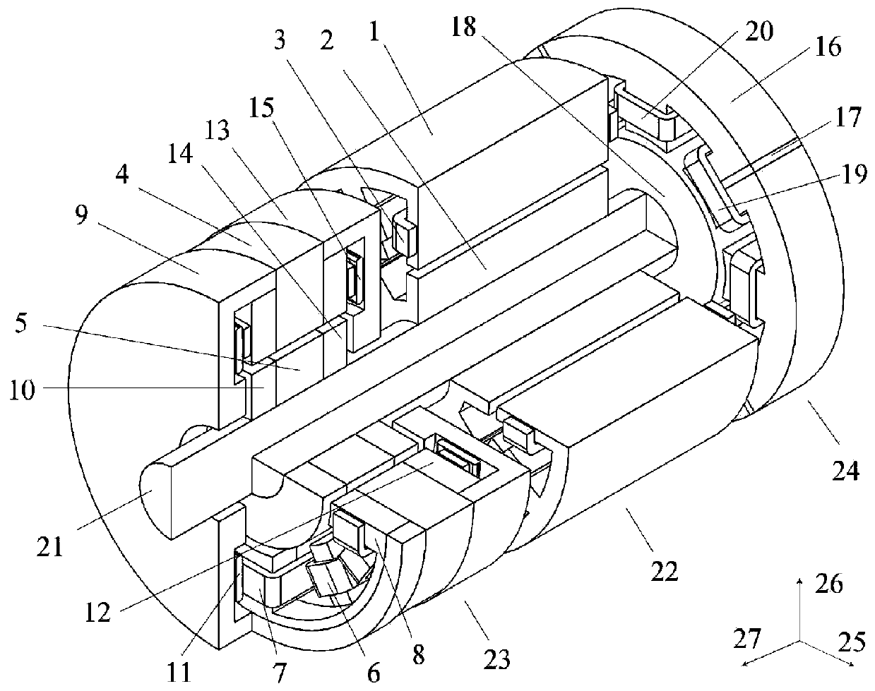
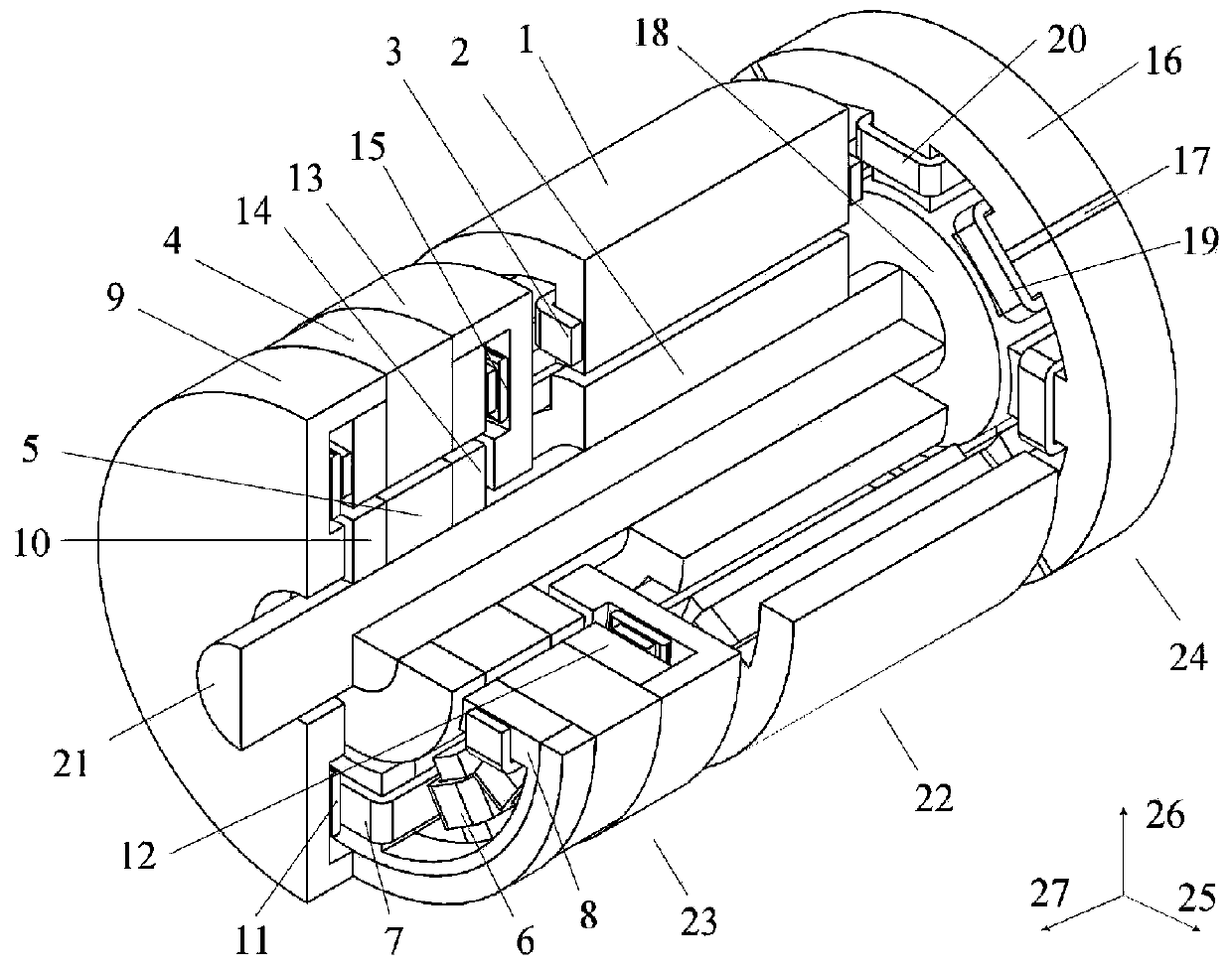
[0069] The technical scheme of a five-degree-of-freedom electromagnetic magnetic levitation switched reluctance motor and control method of the present invention will be described in detail below in conjunction with the accompanying drawings:

[0070] Such as figure 1 As shown, it is a three-dimensional structural schematic diagram of the embodiment 1 of the five-degree-of-freedom electromagnetic magnetic levitation switched reluctance motor of the present invention, wherein, 1 is the stator of the reluctance motor, 2 is the rotor of the reluctance motor, 3 is the armature coil, and 4 is the radial direction Stator Ⅰ, 5 is radial rotor Ⅰ, 6 is radial levitation coil Ⅰ, 7 is bias coil Ⅰ, 8 is bias stator Ⅰ, 9 is axial stator Ⅰ, 10 is axial rotor Ⅰ, 11 is axial Suspension coil I, 12 is offset stator II, 13 is axial stator II, 14 is axial rotor II, 15 is axial suspension coil II, 16 is radial stator II, 17 is non-magnetic separator, 18 is diameter To the rotor II, 19 is the bias...


PUM


Abstract

The invention discloses a five-degree-of-freedom electromagnetic-type magnetic suspension switched reluctance motor and a control method. The motor comprises an electromagnetic-type axial and radial magnetic bearing, a switched reluctance motor and an electromagnetic-type radial magnetic bearing. The switched reluctance motor generates torque to realize rotary operation; the electromagnetic-type axial and radial magnetic bearing generates two radial suspension forces and one axial suspension force, and the electromagnetic-type radial magnetic bearing generates two radial suspension forces, sothat five-degree-of-freedom suspension operation is realized; the bias windings of the two magnetic bearings and the m-phase armature winding of the switched reluctance motor are jointly excited by apower converter, and the torque and bias magnetic flux are generated at the same time. According to the motor and the control method, the electromagnetic conversion efficiency is high, the system integration level and reliability are high, and comprehensive integration of the motor, the magnetic bearing and the control system is achieved; the torque control method is the same as a method of a traditional switch reluctance motor; five suspension winding currents are controlled to adjust five suspension forces, so control variables are few, the control is easy, the suspension power loss is small, and suspension precision is high.

Description

technical field [0001] The invention relates to a five-degree-of-freedom electromagnetic type magnetic levitation switched reluctance motor and a control method thereof, belonging to the field of magnetic levitation switched reluctance motors of motors. Background technique [0002] The magnetic levitation motor system composed of electromagnetic magnetic bearings and switched reluctance motors has strong adaptability to harsh working environments such as high temperature, high humidity, and strong corrosion because there is no permanent magnet in the system. It has unique advantages in applications such as harsh working environments. [0003] In the traditional electromagnetic levitation switched reluctance motor system, the two systems of the electromagnetic magnetic bearing and the switched reluctance motor are controlled separately, and two microprocessors are required to control them separately. There are many control variables, a large power system, high cost, and a hi...

Claims


Application Information

Patent Timeline
Patent Type & Authority Applications(China)
IPC IPC(8): H02K7/09H02K1/14H02K1/24H02P25/08
CPCH02K1/14H02K1/24H02K7/09H02P25/08
Inventor 刘泽远蔡骏魏明霞
Owner 南京埃克锐特机电科技有限公司
Why Eureka
Try Eureka