
Process and plant for thermal treatment in a fluidized bed reactor

A fluidized bed reactor and reactor technology, applied in chemical instruments and methods, heat treatment, chemical/physical processes, etc., can solve the problems of increasing the specific energy of the calcination method, achieve the effect of reducing investment and operating costs, and easy design

Active Publication Date: 2019-07-05
METSO OUTOTEC (FINLAND) OY
View PDF9 Cites 4 Cited by
  • Summary
  • Abstract
  • Description
  • Claims
  • Application Information

AI Technical Summary

Problems solved by technology

This is accompanied by an additional energy loss which increases the specific energy required in the calcination process

Method used


Image

  • Process and plant for thermal treatment in a fluidized bed reactor
  • Process and plant for thermal treatment in a fluidized bed reactor

Examples


Embodiment Construction

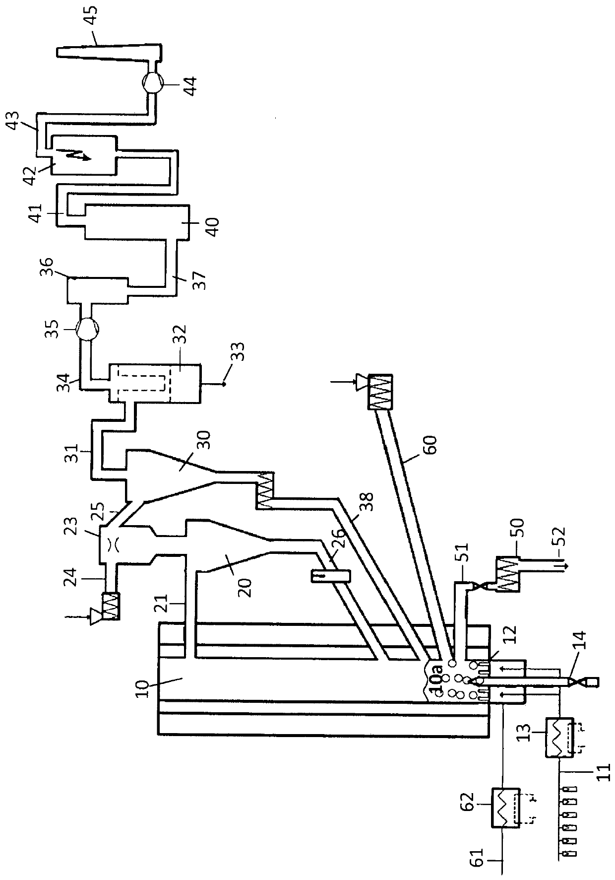
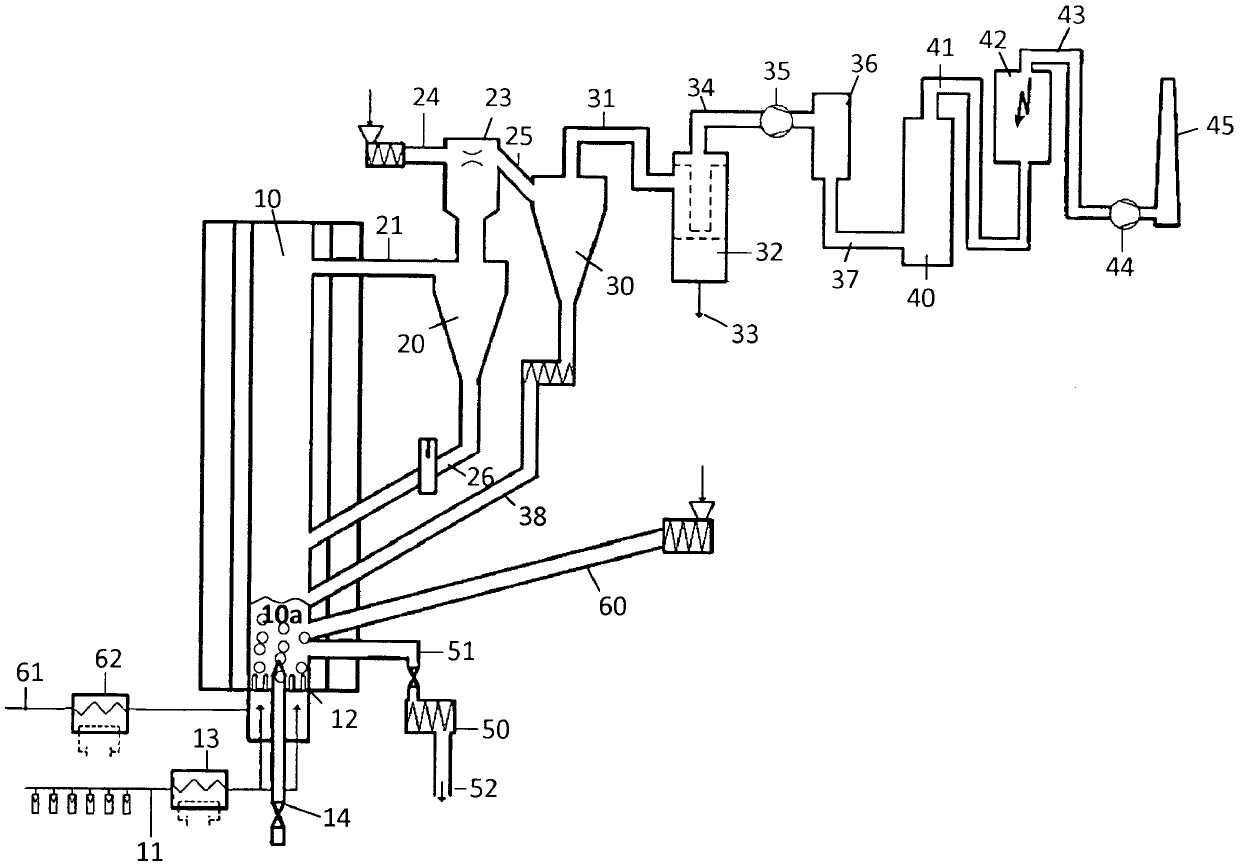
[0069] figure 1 A method of calcining minerals using biogas as fuel and a novel injection system is shown. Gas with the desired composition enters nozzle grate 12 via conduit 11 and fluidizes the material in reactor 10 . Before entering the nozzle grate 12, the air may be heated to the required temperature by an electric preheating system 13. Temperatures were measured at various locations and the data recorded.

[0070] Biogas is injected into the reactor 10 as fuel via the lance 13 . The fuel is combusted in the reactor to thermally treat the solid particles in the fluidized bed 10 .

[0071] The solids entrained by the reactor flue gas in the gas-solid mixture are recycled to the fluidized bed 10a through the conduit 31 and the cyclone separator 20 . The separated solids fraction comprising at least 60% by weight of the solids contained in the discharged gas-solid mixture is recycled to the reactor 10 via conduit 26 . The dust laden gas leaving the cyclone 20 flows via...


PUM


Abstract

The invention describes a process for calcining a mineral comprising the following steps feeding a mineral into a fluidized bed reactor (i), injecting biogas as fuel into the fluidized bed reactor (ii), burning the biogas for generating heat to calcine the mineral (iii), withdrawing calcined mineral from the fluidized bed in the reactor (iv) and withdrawing a mixture of gas and solid particles from a position above the fluidized bed (v).

Description

technical field [0001] The present invention relates to a process and related treatment in a fluidized bed reactor with emphasis on the use of biomass affecting the feed system as well as flue gas treatment. Background technique [0002] Heat treatment, especially calcination of minerals, is a well-known method, which is why the products of this method are widely used. A good example of such a product is kaolin, as shown in WO 2005 / 019349. [0003] Kaolin is a natural industrial mineral with various applications (eg pigments, paper, polymers, cement, cosmetic industry, agriculture and construction). Kaolin calcination is a well-established process based on the thermal treatment of aluminum silicate minerals, usually processed in kilns or hearth furnaces. Since the calcination method depends on a certain calcination time at a certain temperature to improve the whiteness and hardness of the material and its electrical properties, it is crucial to be able to control the tempe...

Claims


Application Information

Patent Timeline
IPC IPC(8): B01J8/18B01J8/24B01J6/00B01J8/00
CPCB01J8/1863B01J6/004B01J8/0055B01J2208/00168B01J2208/00274C09C1/42B01J2208/00415B01J2208/00495B01J2208/0053Y02P20/133
Inventor C·宾得E·加萨菲J·格雷尼格M·沃贝尔
Owner METSO OUTOTEC (FINLAND) OY
Learn More