Vertical-type cooling machine with rectifying device and cooling method

A rectifying device and cooling machine technology, applied in sinter cooling machine and sinter cooling, vertical cooling machine and cooling field, can solve the problems of high air leakage rate of cooling machine, reduce the quality of hot exhaust gas, uneven distribution of material particle size, etc., to achieve Improve the uniformity of cooling, improve the quality of hot exhaust gas, and evenly distribute the airflow

Pending Publication Date: 2019-07-09
ZHONGYE-CHANGTIAN INT ENG CO LTD
View PDF0 Cites 1 Cited by
  • Summary
  • Abstract
  • Description
  • Claims
  • Application Information

AI Technical Summary

Problems solved by technology

No matter which cooling method is used, the cooling machine has problems such as large air leakage rate, high fan power consumption, low sensible heat recovery rate, and low boiler thermal efficiency.
In other words, in the current environment where the market has increasingly stringent requirements for energy saving and green manufacturing in sinter production, the original equipment structure has been difficult to achieve efficient recovery and utilization of sinter sensible heat
At the same time, when the material entering the cooler has particle size segregation in the horizontal direction, the material distributed in the cooler will have uneven particle size distribution in the circumferential direction, which will cause uneven airflow distribution in the cooler, which will eventually affect Cooling uniformity, reducing hot exhaust gas quality

Method used


Image

  • Vertical-type cooling machine with rectifying device and cooling method
  • Vertical-type cooling machine with rectifying device and cooling method
  • Vertical-type cooling machine with rectifying device and cooling method

Examples


Embodiment 1

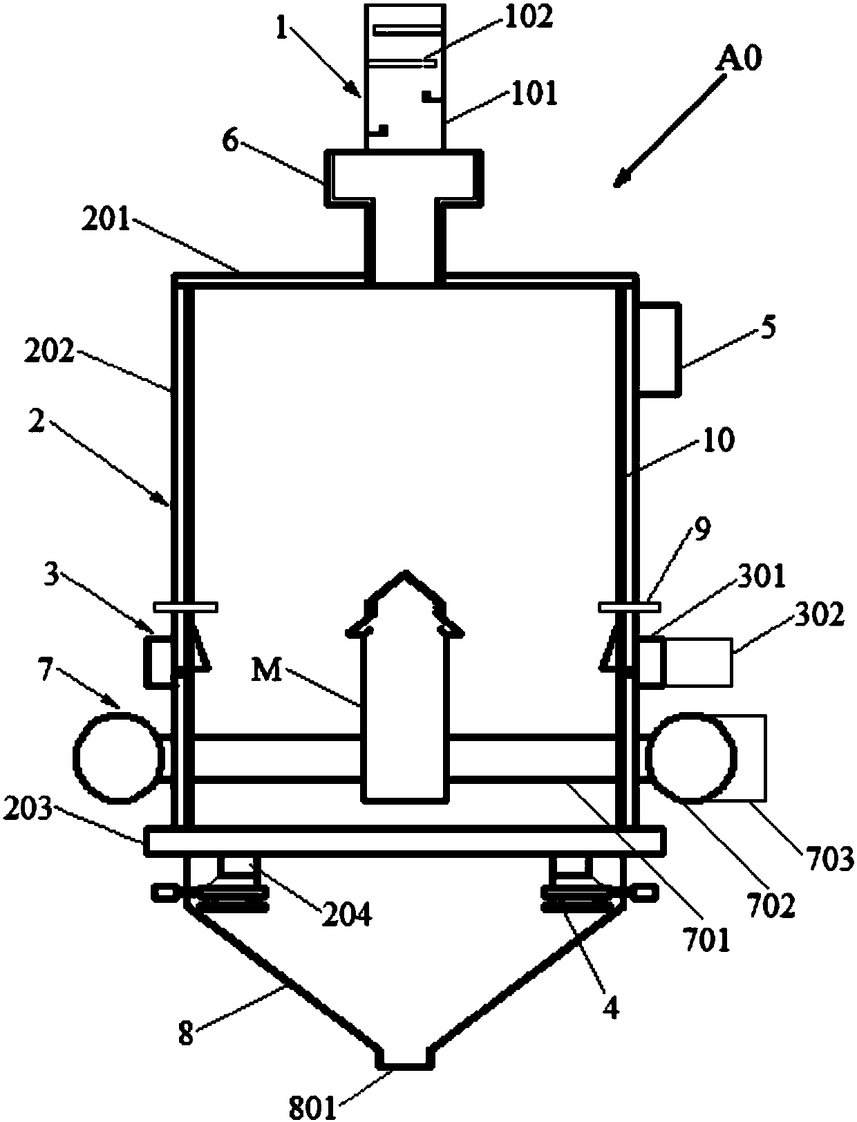
[0089] Such as figure 1 As shown, a vertical cooling machine with a rectifying device, the vertical cooling machine A0 includes a rectifying device 1, a tower body 2, a side air supply device 3, and a discharge device 4. The tower body 2 includes a tower top 201, a tower wall 202, and a tower bottom 203. The tower top 201 is arranged on the top of the tower wall 202. The tower bottom 203 is arranged at the bottom of the tower wall 202. The rectifying device 1 is arranged above the tower top 201 and communicates with the inside of the tower body 2. The side air supply device 3 is arranged in the middle and lower part of the tower wall 202. The bottom 203 is provided with a discharge port 204. The discharge device 4 is arranged below the discharge opening 204. The upper part of the tower wall 202 is provided with a hot air outlet 5. The vertical cooler A0 also includes a cloth device 6. The distributing device 6 is arranged between the rectifying device 1 and the tower body...

Embodiment 2

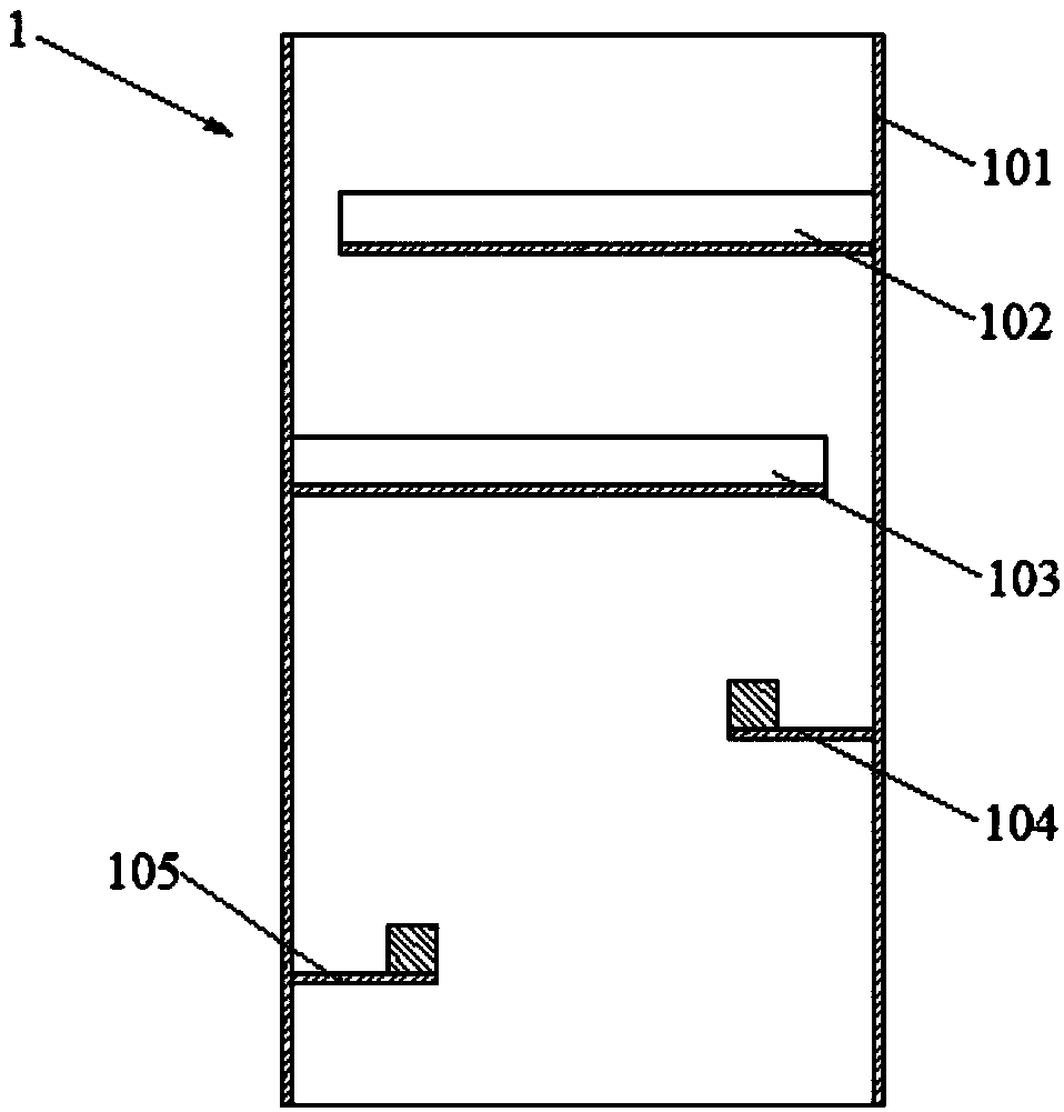
[0097] Such as Figure 5 As shown, embodiment 1 is repeated, except that the rectifying device 1 further includes a second baffle 103. The second baffle 103 is disposed on the inner wall of the housing 101 opposite to the first baffle 102, and the second baffle 103 is located below the first baffle 102. The second baffle 103 is also a concave structure, and its concave opening direction is opposite to the first baffle 102.

Embodiment 3

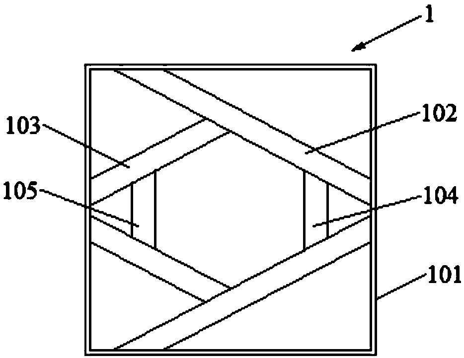
[0099] Such as Figure 2-3 As shown in 6-7, embodiment 2 is repeated, except that the rectifying device 1 further includes a third baffle 104. The third baffle 104 is arranged on the inner wall of the housing 101 opposite to the second baffle 103, and the third baffle 104 is located below the second baffle 103. The third baffle 104 has a plate-shaped structure. The rectifying device 1 further includes a fourth baffle 105. The fourth baffle 105 is disposed on the inner wall of the housing 101 opposite to the third baffle 104, and the fourth baffle 105 is located below the third baffle 104. The fourth baffle 105 also has a plate-shaped structure. The third baffle 104 and the fourth baffle 105 are provided with protrusions at one end of the edge.


PUM

PropertyMeasurementUnit
diameteraaaaaaaaaa
diameteraaaaaaaaaa

Abstract

The invention discloses a vertical-type cooling machine with a rectifying device. The vertical-type cooling machine comprises the rectifying device, a tower body, an edge air supply device and discharging devices. The tower body comprises a tower top, a tower wall and a tower bottom. The tower top is arranged at the top of the tower wall, and the tower bottom is arranged at the bottom of the towerwall. The rectifying device is arranged above the tower top and further communicates with the inside of the tower body. The edge air supply device is arranged on the lower middle portion of the towerwall. The tower bottom is provided with discharging outlets. The discharging devices are arranged below the corresponding discharging outlets. A hot-blast air outlet is formed in the upper portion ofthe tower top or the tower wall. The vertical-type cooling machine disclosed by the invention has the cooling beneficial effects that the cooling speed of agglomerate is low, ton consumption coolingblast capacity is small, the exhausted air amount is relatively small, the exhausted air temperature is high, the heat efficiency of a boiler is high, the cooled exhausted gas can be fully utilized bythe boiler, and the sensible heat recovery rate of the agglomerate can reach about 7%.

Description

Technical field [0001] The invention relates to a sinter cooler and a sinter cooling method, in particular to a vertical cooler with a rectifying device and a cooling method, and belongs to the field of ironmaking and environmental protection. Background technique [0002] In the modern sintering process, "cooling" is one of the more critical processes. After the sintered ore is roasted by the sintering machine, it has formed a high-temperature finished ore. How can it be protectively cooled without affecting its quality and yield, so that it can be sent to the finished ore bin via a belt conveyor, and at the same time The perfect recovery and utilization of the sensible heat energy it carries has always been a problem that has been continuously researched by industry technicians. [0003] At present, sinter cooling mainly adopts traditional belt coolers or ring coolers based on the principle of high-air fast cooling and one-time loading and unloading cooling. No matter which coo...

Claims


Application Information

Patent Timeline
Patent Type & Authority Applications(China)
IPC IPC(8): F27D9/00F27D17/00F27D19/00C22B1/26
CPCC22B1/26F27D9/00F27D17/004F27D19/00F27D2009/0005F27D2019/0003Y02P10/25
Inventor 张震贺新华于耀韬
Owner ZHONGYE-CHANGTIAN INT ENG CO LTD
Why Eureka
Try Eureka