Automatic LED (Light-Emitting Diode) feature parameter collecting system

A technology of automatic collection of characteristic parameters, applied in the direction of measuring electricity, measuring devices, measuring electrical variables, etc., can solve problems such as long aging test process, and achieve the effect of accurate and continuous testing, high reliability and high precision of testing

Pending Publication Date: 2019-07-09
SUZHOU UNIV OF SCI & TECH
View PDF0 Cites 2 Cited by
  • Summary
  • Abstract
  • Description
  • Claims
  • Application Information

AI Technical Summary

Problems solved by technology

Among them, the selection and measurement of LED sample parameters are related to the reliability and stability of the detection. If the traditional method is used, the aging test process is too long, and the collection of electrical parameters is also affected by various factors.

Method used


Image

  • Automatic LED (Light-Emitting Diode) feature parameter collecting system
  • Automatic LED (Light-Emitting Diode) feature parameter collecting system
  • Automatic LED (Light-Emitting Diode) feature parameter collecting system

Examples


Embodiment 1

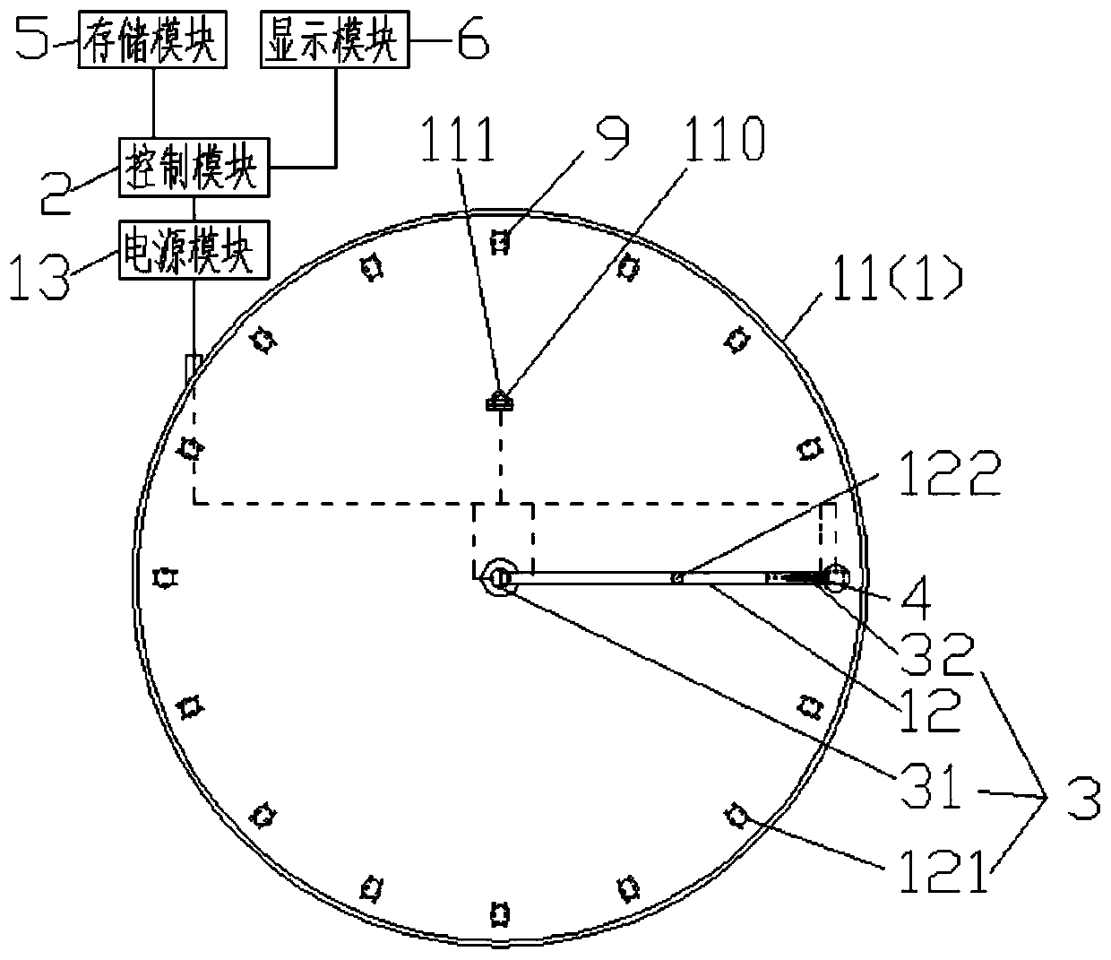
[0025] like figure 1 , an automatic collection system for LED characteristic parameters, which collects characteristic parameters of LED samples 9, including an LED test mechanism 1, a control module 2, an actuator 3, a detection module 4, a storage module 5, a display module 6, and a power supply module 13. The LED test mechanism 1 includes a test bench 11 placed horizontally, a mechanical arm 12 arranged on the test bench 11, and the power supply module 13 is an LED sample 9 and a control module 2, an actuator 3, a detection module 4, and a storage module. 5. The display module 6 supplies power, and the LED sample 9 is placed on the test bench 11. The test bench 11 is provided with a short-circuit mechanism 121 on the side of the LED sample 9, and the short-circuit mechanism 121 is suitable for short-circuiting the LED. catch. The control module 2 is a PLC or a single-chip microcomputer; the LED testing mechanism 1 can be controlled independently or combined with other test...

Embodiment 2

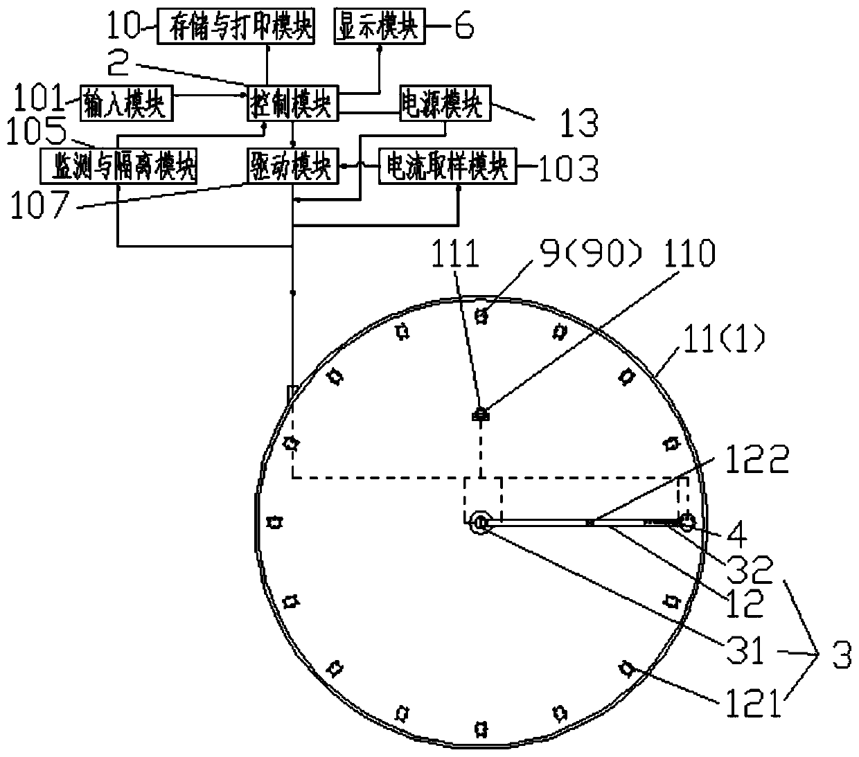
[0032] like figure 2 , Embodiment 2 On the basis of Embodiment 1, the following expansions are made:

[0033] The LED characteristic parameter automatic collection system is integrated in the LED test automatic control system, and the automatic control system conducts a power-on test on a group of LED samples connected in series, and outputs the test current, preferably using a programmable constant current source to output the test current; When a failed sample appears in a group of LED samples, the failed sample is automatically short-circuited, and the number and failure time of the failed sample are recorded until the test cut-off condition is reached. This scheme can automatically short-circuit the failed samples and restore the test, which is convenient and reliable.

[0034] Specifically, in addition to the LED test mechanism 1, control module 2, actuator 3, detection module 4, display module 6, and power module 13 mentioned in Embodiment 1, the LED test automatic con...


PUM


Abstract

The invention discloses an automatic LED (Light-Emitting Diode) feature parameter collecting system. The automatic LED feature parameter collecting system is used for collecting feature parameters ofan LED sample, and comprises an LED testing mechanism, a control module, an implementing mechanism, a detecting module, a storing module, a displaying module and a power module, wherein the LED testing mechanism comprises a testing rack which is placed horizontally, and a mechanical arm which is arranged on the testing rack; the power module is used for supplying power to the LED sample; the LED sample is placed on the testing rack; the mechanical arm is used for detecting the feature parameters of the LED sample by driving the detecting module through a rotation operation and a telescopic operation; the testing rack is provided with a short-circuit mechanism on the LED sample side; and a short circuit mechanism is suitable for the short circuit of the LED sample. The automatic LED featureparameter collecting system has the advantages of simple structure, reliable and stable control mechanism and action mechanism, capability of eliminating the accumulation error, and accurate and durable testing, and is beneficial to popularization and application.

Description

technical field [0001] The invention belongs to the technical field of photoelectric device testing, and in particular relates to an automatic collection system for LED characteristic parameters. Background technique [0002] Light-emitting diodes, or light-emitting LED devices, are a type of semiconductor diode that can convert electrical energy into light energy. LED has excellent characteristics such as high efficiency, pure light color, flexible application, and high light quality. Light-emitting diodes are used as light sources in many photoelectric control equipment and signal displays in electronic equipment. [0003] However, during the use of the LED, due to the influence of the current and the external environment, it will inevitably age. The aging of the LED mainly includes the aging of the chip and the aging of the package. The aging mechanism of the chip includes the strengthening of thermomechanical stress caused by heat accumulation, the expansion of chip cr...

Claims


Application Information

Patent Timeline
Patent Type & Authority Applications(China)
IPC IPC(8): G01R31/26G01M11/02
CPCG01M11/00G01R31/2601
Inventor 石颉申海锋田昌前赵德宇
Owner SUZHOU UNIV OF SCI & TECH
Why Eureka
Try Eureka