Strip line structure for low-pass filter, low-pass filter, and communication device and system

A technology of low-pass filter and communication device, which is applied in the field of low-pass filter, communication device and system, and stripline structure. Poor, unfavorable overall performance of the filter, etc., to achieve the effect of reducing design difficulty, realizing miniaturization, and reducing loss

Pending Publication Date: 2019-07-12
重庆思睿创瓷电科技有限公司
View PDF0 Cites 4 Cited by
  • Summary
  • Abstract
  • Description
  • Claims
  • Application Information

AI Technical Summary

Problems solved by technology

For the ceramic waveguide filter technology that must be used in the 5G era, the traditional solution is to reduce the loss of the ceramic filter part, such as using low dielectric constant ceramic materials, using multi-mode technology, etc., but using low dielectric constant The material will increase the volume and cannot meet customer requirements; the use of multi-mode technology is less cost-effective and the mass production is not high; in contrast, the optimization of the low-pass filter part has been ignored, but the stripline low-pass filter is not without room for optimization
[0005] From the perspective of electronic system design, current density is a very important indicator. The performance of the circuit is closely related to the amount of current, and the current density is determined by the size and shape of the conductor. The circuit layer in the stripline low-pass filter Its essence is to form a metal layer with a specific pattern (used to form a stripline resonator circuit). The area will be more confined near the surface, which will increase the current density. If the current density is too high, the loss will also increase, which will have adverse consequences on the overall performance of the filter.

Method used


Image

  • Strip line structure for low-pass filter, low-pass filter, and communication device and system
  • Strip line structure for low-pass filter, low-pass filter, and communication device and system
  • Strip line structure for low-pass filter, low-pass filter, and communication device and system

Examples


Embodiment Construction

[0028] The following is further described in detail through specific implementation methods:

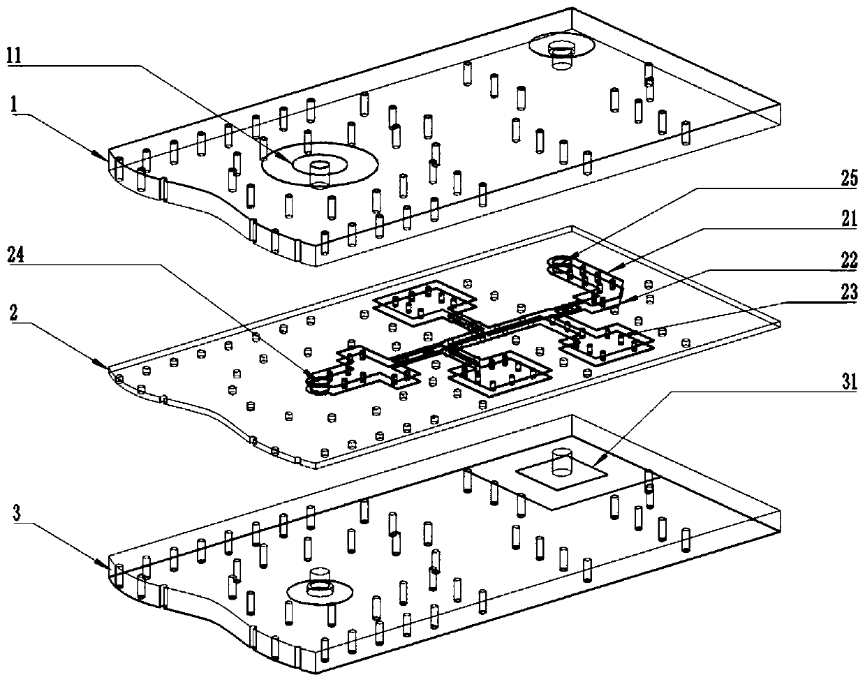
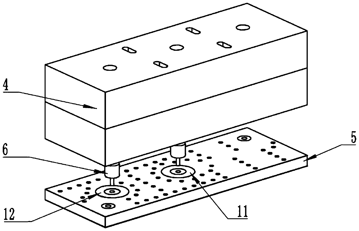
[0029] The reference signs in the drawings of the description include: upper substrate 1, second pad 11, third pad 12, intermediate substrate 2, upper stripline sublayer 21, lower stripline sublayer 22, inter-sublayer connection The via hole 23 , the input signal via hole 24 , the output signal via hole 25 , the lower substrate 3 , the first pad 31 , the dielectric waveguide filter 4 , the low pass filter 5 , and the probe 6 .

[0030] figure 1 shows a schematic structural view of a low-pass filter adopting the stripline structure disclosed by the present invention for the low-pass filter, the low-pass filter is formed by bonding three substrates, including an upper substrate 1 , the intermediate substrate 2 and the lower substrate 3, the upper stripline sublayer 21 and the lower stripline sublayer 22, the connection via hole 23 between the sublayers, the input signal via hole 24 an...


PUM


Abstract

The invention relates to the technical field of filters, and in particular to a strip line structure for a low-pass filter. The strip line structure comprises at least two longitudinally-stacked and parallel strip line sub-layers. The respective strip line sub-layers have the same planar pattern. The two-dimensional dimensions of the respective strip line sub-layers are in an equally proportionalscaling relationship. The strip line sub-layer having small area is completely located within the coverage of the strip line sub-layer having large area. The gaps between the strip line sub-layers arefilled with dielectric base layers. The strip line sub-layers are coupled to each other. The invention also discloses a low-pass filter using the strip line structure, and a communication device andsystem. The strip line structure reduces the loss of a signal during circuit transmission, thereby achieving a purpose of reducing the system loss. The miniaturization of an apparatus can be further achieved.

Description

technical field [0001] The invention relates to the technical field of filters, in particular to a stripline structure for a low-pass filter, a low-pass filter, a communication device and a system. Background technique [0002] With the advent of the 5G communication era, the requirements for the weight and volume of base station equipment are getting smaller and smaller. Due to the advantages of miniaturization, low loss and good temperature characteristics, dielectric filters have become an inevitable option for base station equipment in the 5G era. Among them The application of ceramic waveguide filter is the most representative. In the practical application of ceramic waveguide filters, it must be used together with a low-pass filter for far-end suppression to form a filter component. The final performance of this filter component depends not only on the ceramic waveguide filter itself, but also on the low-pass Pass filters are closely related. [0003] The low-pass fi...

Claims


Application Information

Patent Timeline
Patent Type & Authority Applications(China)
IPC IPC(8): H01P1/203
CPCH01P1/203
Inventor 何进军蔡文新陈鹏韦俊杰
Owner 重庆思睿创瓷电科技有限公司
Why Eureka
Try Eureka