Dust collector motor deceleration method

A vacuum cleaner and motor controller technology, applied in the direction of a single motor speed/torque control, collectors, electric vehicles, etc., can solve the problem of long deceleration time, and achieve the effect of increasing the use time, improving the user experience, and shortening the deceleration time.

Active Publication Date: 2019-07-12
WUXI NEWSTART CONTROLS TECH CO LTD
View PDF6 Cites 3 Cited by
  • Summary
  • Abstract
  • Description
  • Claims
  • Application Information

AI Technical Summary

Problems solved by technology

Although the deceleration time is shorter than the first method, the deceleration time is still longer

Method used


Image

  • Dust collector motor deceleration method
  • Dust collector motor deceleration method
  • Dust collector motor deceleration method

Examples


Embodiment Construction

[0022] The present invention will be described in detail in conjunction with accompanying drawing now. This figure is a simplified schematic diagram only illustrating the basic structure of the present invention in a schematic manner, so it only shows the components relevant to the present invention.

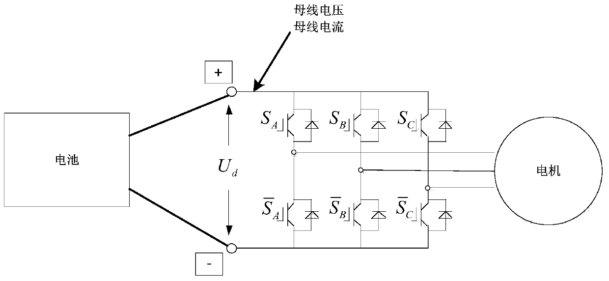
[0023] Such as figure 1 Shown is a schematic diagram of the inverter part of a vacuum cleaner motor controller of the present invention, including a three-phase permanent magnet synchronous motor, a power supply battery and a motor controller, and the single-chip microcomputer on the motor controller controls 6 switching tubes to switch regularly. The motor runs. The "bus voltage" and "bus current" of the motor controller are equal to the voltage and current of the battery.

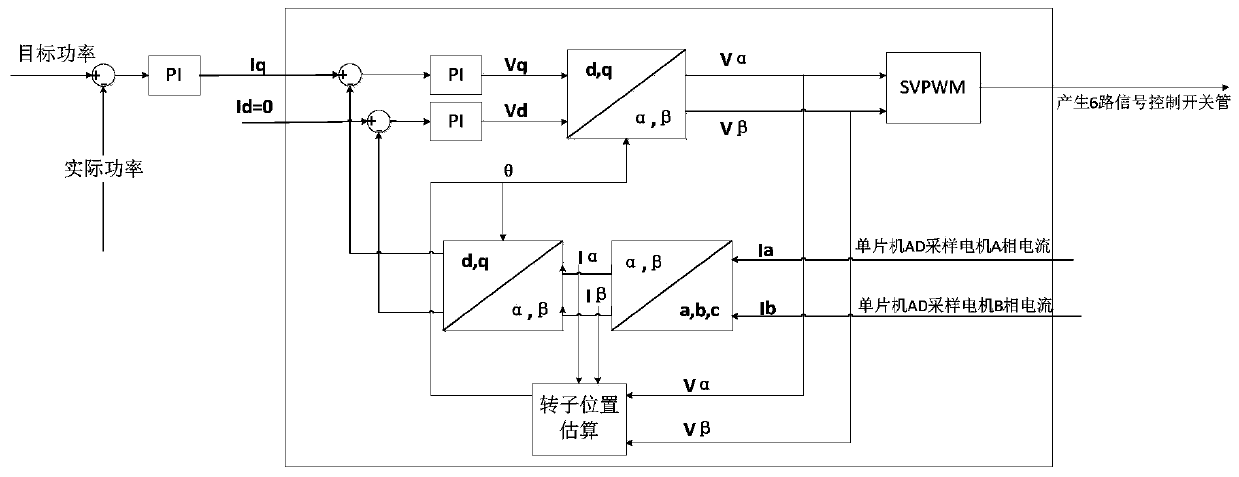
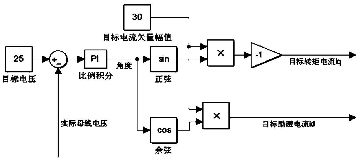
[0024] Such as figure 2 Shown is the vector control algorithm when the motor is running normally, and this algorithm is common. The input to the algorithm is the target torque current i d and the targ...


PUM


Abstract

The invention provides a dust collector motor deceleration method. When the shutdown deceleration is needed, the working switch of a dust collector is released, and a single chip microcomputer receives a deceleration signal and enters a deceleration mode; at the moment, the single chip microcomputer determines whether the rotating speed of the motor is zero or not, if not, the single chip microcomputer controls the motor controller to output a negative torque to decelerate the motor, namely, the target torque current iq is negative, when the iq is negative, a three-phase permanent magnet synchronous motor works in a power generation state, at the moment, a bus voltage rises, and the battery is charged when the bus voltage is higher than the battery voltage; and if the rotating speed of themotor is zero, the dust collector stops working. The method can greatly shorten the deceleration time, namely shorten the noise duration time, and can improve the user experience. The kinetic energygenerated when the motor decelerates can be converted into electric energy to charge the battery, so that the service time of the dust collector is prolonged.

Description

technical field [0001] The invention relates to the technical field of vacuum cleaner motor control, in particular to a method for decelerating a vacuum cleaner motor. Background technique [0002] At present, more and more three-phase permanent magnet synchronous motors are used in vacuum cleaners. At present, the motor deceleration method of vacuum cleaners is sliding free deceleration. Due to the long deceleration time, the noise will continue until the motor speed is 0, and the user will hear a long time Noise, bad experience. [0003] In the prior art, when it is necessary to stop and decelerate, there are generally two common deceleration methods: the first method is to directly turn off the switch tube, the software stops controlling the motor, and the motor decelerates naturally. When this method decelerates, there is no current in the motor, and the kinetic energy of the motor is completely consumed by frictional resistance, so this method decelerates slowly. The ...

Claims


Application Information

Patent Timeline
Patent Type & Authority Applications(China)
IPC IPC(8): H02P6/08H02J7/32
CPCH02J7/32H02P6/08
Inventor 李潮州倪瑞
Owner WUXI NEWSTART CONTROLS TECH CO LTD
Why Eureka
Try Eureka