Enhanced denitrification reactor used for advanced denitrification and advanced denitrification method of reactor

A deep denitrification and reactor technology, applied in chemical instruments and methods, water/sludge/sewage treatment, water pollutants, etc., can solve the problems of short process automation, large floor area, troublesome management, etc., to achieve Increased residence time, high degree of automation, and short process effects

Active Publication Date: 2019-07-16
DONGGUAN DONGRI WATER TREATMENT TECH
View PDF6 Cites 2 Cited by
  • Summary
  • Abstract
  • Description
  • Claims
  • Application Information

AI Technical Summary

Problems solved by technology

[0013] Aiming at the problems existing in the prior art, the present invention provides an enhanced denitrification reactor for deep denitrification and a deep denitrification method thereof. The reactor and method adopt the principle of biological denitrification, and have good denitrification effect and flow process It has the advantages of short length and high degree of automation, and also overcomes the shortcomings of traditional biological deep denitrification operation management, low efficiency at low temperature, large floor area, and the need to add additional carbon sources.

Method used


Image

  • Enhanced denitrification reactor used for advanced denitrification and advanced denitrification method of reactor
  • Enhanced denitrification reactor used for advanced denitrification and advanced denitrification method of reactor
  • Enhanced denitrification reactor used for advanced denitrification and advanced denitrification method of reactor

Examples


Embodiment 1

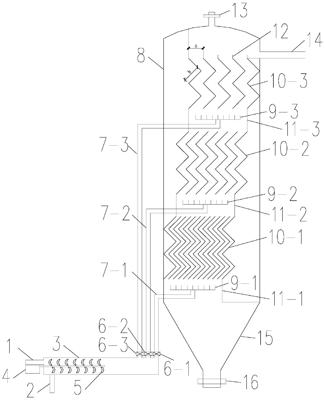
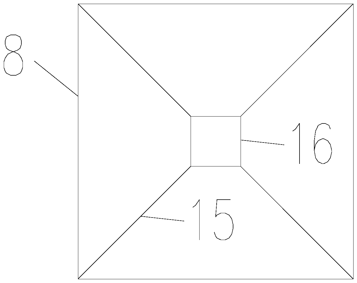
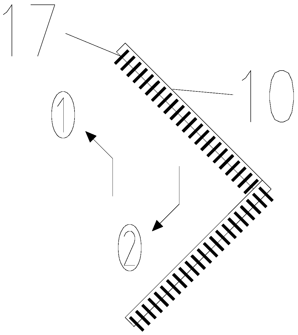
[0063] An enhanced denitrification reactor for deep denitrification, the schematic diagram of its cross-sectional structure is shown in figure 1 , including water inlet pipe 1, air inlet pipe 2, pre-stirring reactor 3, first water distribution pipe 7-1, second water distribution pipe 7-2, third water distribution pipe 7-3, reactor shell 8, first water distribution pipe System 9-1, second water inlet and distribution system 9-2, third water inlet and distribution system 9-3, multi-stage baffle hanging material board, first water retaining plate 11-1, second water retaining plate 11-2 , the third water retaining plate 11-3, overflow plate 12, exhaust valve 13, outlet pipe 14, sludge bucket 15, mud discharge valve 16 and fiber filler 17;

[0064] in,

[0065] The pre-stirred reactor 3 includes a pre-stirred reaction shell, a stirred flow device 5 and a motor 4, the water inlet pipe 1 is connected to the pre-stirred reactor shell, and the described air inlet pipe 2 is connected t...


PUM

PropertyMeasurementUnit
widthaaaaaaaaaa
diameteraaaaaaaaaa
heightaaaaaaaaaa

Abstract

The invention provides an enhanced denitrification reactor used for advanced denitrification and an advanced denitrification method of the reactor, and belongs to the field of sewage treatment equipment manufacturing. The enhanced denitrification reactor used for advanced denitrification comprises a water inlet pipe, a gas inlet pipe, a pre-stirring reactor and the like; the water inlet pipe and the gas inlet pipe are connected with a shell of the pre-stirring reactor, and a stirring flow-pushing device is arranged in the shell of the pre-stirring reactor and connected with a motor through a rotating shaft; one end of each branch water pipe communicates with the pre-stirring reactor, and the other end is connected to one corresponding influent water distribution system; and two sides of every two adjacent-stage baffling material-hanging plates are connected by one corresponding water blocking plate, each influent water distribution system is arranged in one corresponding water blockingplate, an overflow plate is arranged at the water outlet end in a water flow direction and connected with one end of a nth-stage baffling material-hanging plate, and the water outlet pipe is arrangedat one side of the overflow plate and connected with a reactor outer shell. When the reactor provided by the invention is adopted for inflowing water, advanced denitrification is performed by a fibrous filler of the baffling material-hanging plates, and the reactor adopts a biological denitrification principle, and has the advantages of a good denitrification effect, a short process and a high automation degree.

Description

technical field [0001] The invention belongs to the field of sewage treatment equipment manufacturing, and in particular relates to an enhanced denitrification reactor for deep denitrification and a deep denitrification method thereof. Background technique [0002] The regeneration and utilization of sewage is often inseparable from nitrogen and phosphorus removal technology. This is because the traditional secondary biological treatment technology of urban sewage aims to reduce the concentration of carbon-containing organic matter and suspended solids expressed in comprehensive indicators of BOD5 and COD in sewage. Nitrogen and phosphorus can only remove the amount taken up by bacterial cells due to physiological needs. Usually, the removal rate of nitrogen after secondary treatment is only 20% to 40%, the removal rate of phosphorus is only 10% to 30%, and most of nitrogen and phosphorus have not been removed. When recycled sewage with high nitrogen and phosphorus content ...

Claims


Application Information

Patent Timeline
Patent Type & Authority Applications(China)
IPC IPC(8): C02F9/14C02F101/16
CPCC02F3/30C02F3/302C02F3/301C02F1/00C02F2101/16C02F2101/163
Inventor 于鹏飞郜玉楠何亚婷
Owner DONGGUAN DONGRI WATER TREATMENT TECH
Why Eureka
Try Eureka