Electro-optic intensity modulator chirp parameter testing method based on phase comparison

A technology of electro-optic intensity modulation and phase modulator, which is applied in the field of microwave photonics, can solve problems such as the inability to measure chirp parameters, and achieve the effect of high-precision low-frequency detection

Active Publication Date: 2019-07-16
UNIV OF ELECTRONICS SCI & TECH OF CHINA
View PDF6 Cites 13 Cited by
  • Summary
  • Abstract
  • Description
  • Claims
  • Application Information

AI Technical Summary

Problems solved by technology

[0003] At present, the methods for measuring the chirp parameters of electro-optical intensity modulators with Mach-Zehnder structures are roughly divided into electrical domain measurement methods and optical domain measurement methods. The typical representative of optical domain measurement methods is spectral analysis (Y Q Shi, L S Yan, A EWillner. High-speed electro-optic modulator characterization using opticspectrum analysis.Journal of Lightwave Technology.2003,21(10):2358-23:NCourjal and J M Dudiley.Extinction-ratio-independent method for chirpmeasurements of Mach-Zehnder0ptics.Express modulators 2004,12(3):442-448.), this method utilizes the optical carrier in the spectrum and the power ratio of the sideband to obtain the chirp parameter of the electro-optic intensity modulator, but is limited by the resolution of the wavelength of the commercial spectrum analyzer ( 0.01nm) limitation and the influence of the laser line width, it is impossible to accurately measure the chirp parameters in the low frequency range; the electrical domain measurement method includes the optical frequency discrimination method (J Provost and F Grillot. Measuring the Chirp and the Linewidth Enhancement Factor of Optoelectronic Devices with a Mach-Zehnder Interferometer.IEEE Photonics Journal.2011,3(3):476-488:J SBakos,G P Djotyan,P N.Ignacz,el al.Generation of frequency-chirped laserpulses by an electro-optic amplitude modulator. Optics and Lasers in Engineering.2009,47(1):19-23.), heterodyne method (E Rogersj, J L Carini, J A Pechkis, elal.Characterization and compensation of the residual chirp in a Mach-Zehnder-type electro-optical intensity modulator. Optics Express. 201 0,18(2):1166-1176; D J Krause and J C Cartledge.Technique for Measuring the Optical PhaseTransfer Function.IEEE Photonics Journal.2004,16⑶:1915-1917.), fiber optic transmission method (FDevaux, Y Sorel and J F Kerdiles .Simple measurement of fiber dispersion and ofchirp parameter of intensity modulated light emitter.Journal of LightwaveTechnology.1993,11(12):1937-1940.), wherein the optical frequency discrimination method uses the interferometer method to convert the amplitude-frequency and phase of the device under test The frequency response is extracted to measure chirp parameters, but the interferometer is greatly affected by temperature, and has high requirements on the bandwidth and resolution of the free spectral range (FSR) of the interferometer, and the adjustment is complicated; the heterodyne method uses Optical heterodyne technology measures the ratio of the phase and amplitude information of the modulator to directly obtain the chirp parameters, but is affected by the stability of the laser and is limited to low-bandwidth time-domain measurements; the optical fiber transmission method uses the intensity-modulated optical signal in the dispersion fiber Propagation characteristics, easily affected by fiber length and environment

Method used


Image

  • Electro-optic intensity modulator chirp parameter testing method based on phase comparison
  • Electro-optic intensity modulator chirp parameter testing method based on phase comparison
  • Electro-optic intensity modulator chirp parameter testing method based on phase comparison

Examples


Embodiment 1

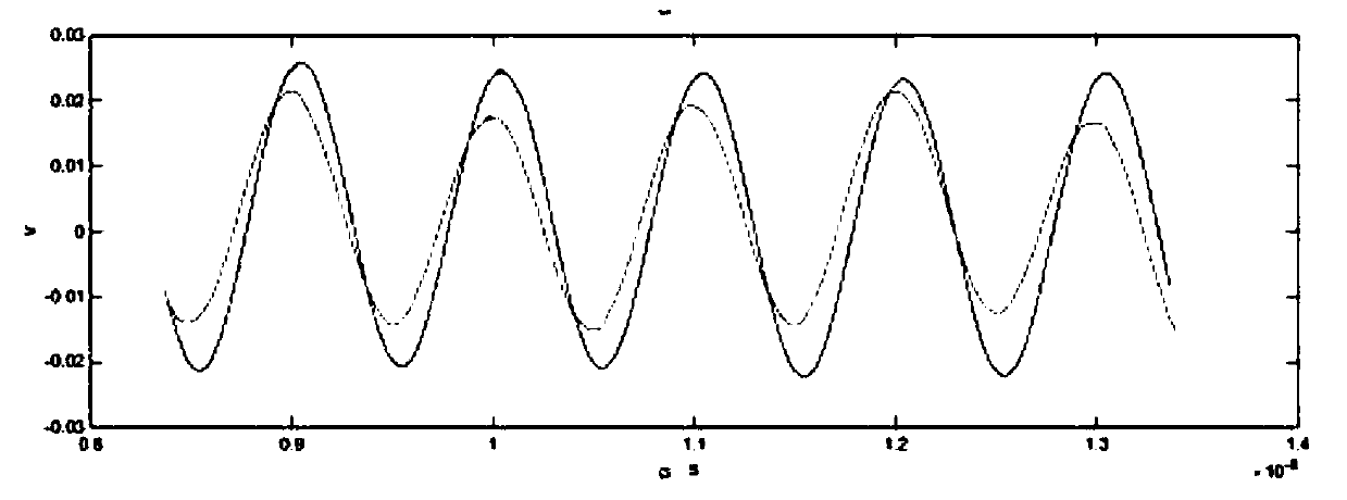
[0053] Measure the 3GHz chirp parameters of the electro-optical intensity modulator, and adjust the frequency generated by microwave signal source 1 to f 1 =3GHz, microwave signal source 2 generates frequency f 2 =1.93GHz, f s =70MHz, satisfying the fixed value f i =(f 1 -f 2 )-f s = 1GHz. Only the 1GHz fixed electrical signal is filtered out through the fixed electrical filter without other harmonic components, and the time domain waveform of the signal is extracted through the oscilloscope. figure 2 Correspondingly adjust the bias voltage twice to filter out the change of the time-domain waveform of the 1GHz signal.

[0054] First calculate the splitting ratio γ of the upper and lower arms of the MZM. Adjust the DC bias to the maximum bias point and the minimum bias point, and measure the maximum value P of the MZM output optical power through an optical power meter max and minimum P min . In the experiment, the extinction ratio of the electro-optic modulator used...


PUM


Abstract

The invention discloses an electro-optic intensity modulator chirp parameter testing method based on phase comparison. According to the method, a broadband high precision electro-optic modulator chirpparameter testing requirement can be satisfied, moreover, the problem of calibrating a photoelectric detector in a test is avoided, low frequency testing of electro-optic modulator chirp parameters is realized through utilization of a frequency shift heterodyne structure, and usage of a high frequency bandwidthphotoelectric detector is avoided. An optical carrier is input into the frequency shiftheterodyne structure and is divided into two. The optical carrier of an upper arm is modulated through utilization of a to-be-tested electro-optic modulator. The optical carrier of a lower arm is subjected to frequency shift andis modulated through an auxiliary phase modulator. Two ways of optical signals are beaten by the photoelectric detector and are converted into electric signals. The electric signals are filtered through utilization of a fixed electric filter to obtain the electric signal with a specific frequency. A time domain waveform of the electric signals is obtained through utilization of an oscilloscope. Through two times of adjustment of a bias voltage of the to-be-tested electro-optic intensity modulator, the phase difference of the electric signal with the specific frequency is observed, and the phase difference is computed to obtain chirp parameters of the electro-optic intensity modulator. A frequency of a radiation frequency signal loaded to the to-be-tested modulator is changed. The above-mentioned process is repeated, and the chirp parameters of the electro-optic intensity modulator at different modulation frequencies can be tested.

Description

technical field [0001] The invention relates to the technical field of microwave photonics, in particular to a method for measuring chirp parameters of an electro-optic intensity modulator. Background technique [0002] With the development trend of high-speed, wide-band and long-distance transmission in optical fiber communication systems, electro-optic intensity modulators have become one of the key components of high-speed optical fiber communication systems. Due to the asymmetry of the waveguide structure and the different driving voltage losses of the upper and lower arms of the traditional Mach-Zehnder waveguide structure electro-optical intensity modulator, a chirp closely related to the fiber dispersion and the optical fiber intensity modulator is formed during the intensity modulation process. The chirp parameter has become an important factor limiting high-speed long-distance transmission. Therefore, in order to improve the overall transmission performance of the o...

Claims


Application Information

Patent Timeline
Patent Type & Authority Applications(China)
IPC IPC(8): G01M11/02G02F1/21
CPCG01M11/0292G02F1/21G02F1/212
Inventor 张尚剑金奇峰王梦珂何禹彤张旨遥张雅丽刘永
Owner UNIV OF ELECTRONICS SCI & TECH OF CHINA
Why Eureka
Try Eureka