
Rotor position estimation method suitable for surface-mounted type permanent magnet synchronous motor

A permanent magnet synchronous motor, rotor position technology, applied in motor control, electronic commutation motor control, electrical components and other directions, can solve the problem of high complexity, and achieve the effect of reducing impact, avoiding phase lag, and reducing initial error

Active Publication Date: 2019-07-19
TAIYUAN UNIVERSITY OF SCIENCE AND TECHNOLOGY
View PDF4 Cites 5 Cited by
  • Summary
  • Abstract
  • Description
  • Claims
  • Application Information

AI Technical Summary

Problems solved by technology

The high-frequency injection method displays the spatial saliency of the rotor by adding a continuous high-frequency excitation signal, and realizes the identification of the rotor position. This method has high complexity and is not suitable for the control of the high-speed area of ​​the motor.

Method used


Image

  • Rotor position estimation method suitable for surface-mounted type permanent magnet synchronous motor
  • Rotor position estimation method suitable for surface-mounted type permanent magnet synchronous motor
  • Rotor position estimation method suitable for surface-mounted type permanent magnet synchronous motor

Examples


Embodiment Construction

[0037] Such as figure 1 Shown, the concrete realization steps of the present invention are as follows:

[0038] The mathematical model of the surface-mounted permanent magnet synchronous motor is established, and its model in the stationary coordinate system satisfies the following formula:

[0039]

[0040] Among them: R and L are stator resistance and inductance respectively; i α and i β are the stator current components on the α-axis and β-axis respectively; u α and u β are the stator voltage components on the α-axis and β-axis respectively; e α and e β are the back EMF components on the α-axis and β-axis respectively; the back EMF e α ,e β satisfy the following formula:

[0041]

[0042] Among them, ψ f is the permanent magnet flux linkage, ω e and θ e are the electrical angular velocity and electrical angle of the rotor, respectively.

[0043] Based on the stationary coordinate system, construct a low-pass filter Q(s), and introduce a first-order inertia...


PUM


Abstract

The invention belongs to the field of motor control, and particularly relates to a rotor position estimation method suitable for a surface-mounted type permanent magnet synchronous motor; the method comprises the following steps that a surface-mounted type permanent magnet synchronous motor mathematical model is established; a low-pass filter is constructed on the basis of a static coordinate system, a voltage signal passes through the low-pass filter to obtain a measurable signal, an auxiliary filter is constructed, an observer is constructed, and the square of the counter electromotive forcefrequency is estimated, the relation between the counter electromotive force and the rotor frequency is established by means of a reverse recursion mode, and then the position information of the rotor is directly obtained according to a trigonometric function. According to the method, only one parameter solving is involved, so that the calculation amount is reduced, and relatively high asymptoticconvergence rate and relatively strong robustness are achieved, the problem of switching buffeting and phase lag caused by a sliding mode observer is avoided, and the influence of noise on the estimation result is lowered.

Description

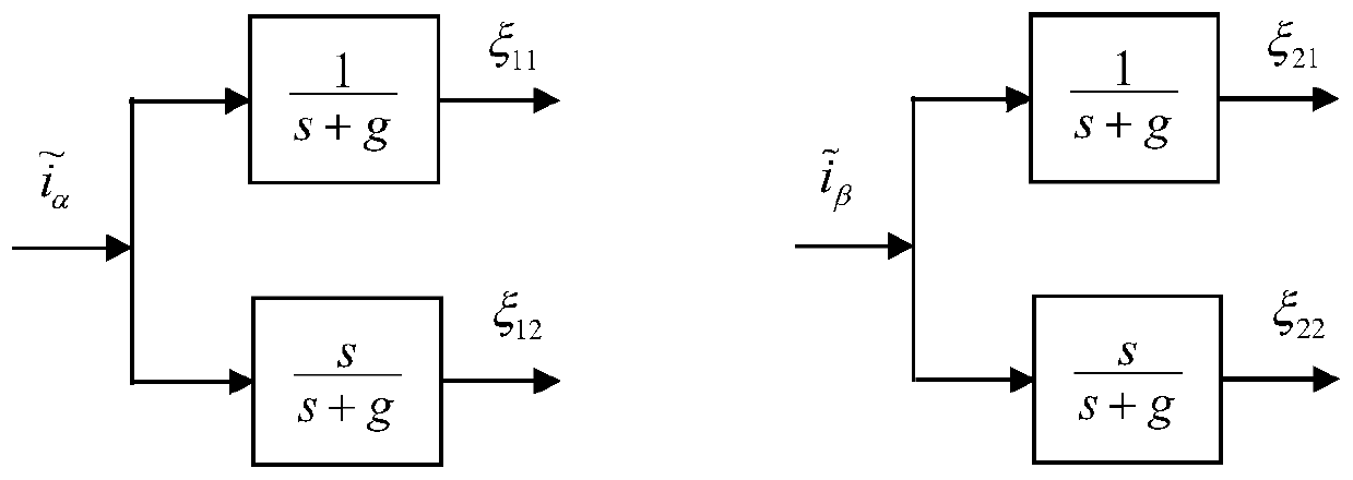
technical field [0001] The invention belongs to the field of motor control, and in particular relates to a method for estimating the rotor position of a surface-mounted permanent magnet synchronous motor. Background technique [0002] In a high-performance motor servo system, in order to obtain an accurate motor rotor position signal, it is generally necessary to install a position sensor such as a photoelectric encoder to feed back the rotor position signal, thereby realizing closed-loop control. However, with the improvement of control requirements, the use of position sensors will lead to an increase in system cost and a more complex hardware structure, which reduces reliability and cannot be used in harsh environments. The above problems greatly restrict the application of permanent magnet synchronous motors . [0003] At present, the main common rotor position estimation methods include sliding mode observer method, extended Kalman filter method, model reference adapti...

Claims


Application Information

Patent Timeline
IPC IPC(8): H02P6/182H02P6/34
CPCH02P6/182H02P6/34H02P2203/03
Inventor 文新宇孙金刚傅荣王娟李泽清张井岗
Owner TAIYUAN UNIVERSITY OF SCIENCE AND TECHNOLOGY
Learn More